
Current Research in Environmental Science and Ecology Letters(CRESEL)
ISSN: 2997-3694 | DOI: 10.33140/CRESEL


Research Article - (2024) Volume 1, Issue 1
Studying Several Parameters on Unreinforced Masonry Infill Walls R C Framed Structure by Seismostruct Program
2Assistant lecturer at Civil Engineering Department, Bilbeis High Institute, Bilbeis, Egypt
3Professor of Structural Engineering at Zagazig University, Zagazig, Egypt
Received Date: Jan 18, 2024 / Accepted Date: Feb 28, 2024 / Published Date: Mar 07, 2024
Copyright: ©Â©2024 Mohamed Metwaly, et al. This is an open-access article distributed under the terms of the Creative Commons Attribution License, which permits unrestricted use, distribution, and reproduction in any medium, provided the original author and source are credited.
Citation: Selim, M., Metwaly, M., Elshamy, E. (2024). Studying Several Parameters on Unreinforced Masonry Infill Walls R.C framed Structure by Seismostruct Program. Curr Res Env Sci Eco Letters, 1(1), 01-07.
Abstract
Reinforced concrete infilled-frames (IF) are commonly used in buildings in the world nowadays. They are often built schools, offices, dwellings, and hospitals, and other kinds of residential and public buildings. The infilled is generally considered a nonstructural element and is ignored in design and analysis despite his strong interaction with the bounding RC frame. Unreinforced Masonry infill walls (URM) are commonly used in the Reinforced Concrete (RC) framed structures as interiors and exterior partition walls. In this research, the behavior of infilled frames is inspected through studying eight frame models were studying several parameters on unreinforced masonry infill walls R.C framed structure such as bare frame (BF), infilled- frame (IF), infill panel with different compressive strength and infill panel with different thickness. Verification studies are performed on one previous experimental works through nonlinear pushover analysis. The analysis showed that increase compressive strength of infill panel increase capacity and thickness of infill panel increase capacity.
Keywords
Bare Frame, Infilled-Frame, Unreinforced Masonry, Infill Panel
Introduction
Masonry infill wall is a common construction form in semi- urban and urban areas; it is playing an important role in engineering structures. Nevertheless, due to low crack resistance and brittle. The masonry structure exposed to be damaged or even collapsed in earthquakes with economic loss and massive casualtie [1-4]. Structural members have significant effects on seismic performance levels of reinforced concrete (RC) buildings. Infilled wall frames improve ductility, stiffness, and energy absorptions of structural systems [5]. The infill walls can be modeled by different numerical techniques such as micro, meso, and macro modeling [6,7]. Infilled frames damage is caused by the serious interaction between masonry infills and bounding frames. When the frames have full contact infill condition, these frames are not able to fully develop the inherent ductile behaviors under lateral excitations. Although the frames are fully in contact, Infilled frames suffer serious shear damage at the regions of beam-column ends or beam-column joints. This research verification study was performed to verify the results between experimental and analytical and studying four models under nonlinear pushover analysis was carried out using displacement controlled monotonic loading using the applied effect of infill (uniformly distributed load F) as the lateral load pattern.
Numerical Analysis and Verification Models
Several computer programs packages have been developed to solve finite element problems. SeismoStruct, ANSYS, NASTRAN, ADINA, LS-DYNA, MARC, SAP, COSMOS, ABAQUS, and NISA are some of the most used packages. The most recent version of SeismoStruct 2021 was selected for use in this research work [8]. In this research verification studies are performed on previous research titled "A novel macro model for prediction of shear failure in columns of masonry infilled RC frames under earthquake loading" [9]. SeismoStruct program is used to perform the analysis of the selected research. Inelastic displacement-based frame elements have been used to simulate beams and columns in SeismoStruct. The experimental analysis for the bare frame (BF) and infilled frame (IF) [9]. This frame filled with the façade masonry panels is a reinforced concrete frame made up of two beams and two columns. The frame has been modeled in the SeismoStruct program. Inelastic displacement-based frame elements divided into 150 fibers have been used for modeling beams and columns. To evaluate the adverse effects of infills and to understand the recommendations of the Indian seismic standards for the design of masonry infilled RC frames, an experimental study was undertaken by the authors [9]. The relevant results of the experimental study are briefly discussed here. The material properties for concrete and reinforcing bars were obtained by compressive tests on concrete cubes and tension tests on bars, respectively. The tests on masonry and its constituents include testing of fly brick units, mortar cubes, masonry prisms, and masonry Wallets. Three types of frames were considered: bare frame (BF), frame infilled with solid Fly ash bricks and using low strength bars for reinforcement (IF-FB1), and frame infilled with Fly ash bricks and using high strength bars for reinforcement (IF-FB2). The major difference between the two infilled frame specimens was that the shear capacity of the column sections in the case of IF- FB2 was enhanced by approximately two times by using high strength bars.

Figure 1: Reinforcement Details of the RC Frame [9].
|
Material |
Property |
Notation |
Value |
|
|
Concrete |
Elastic modulus |
Ec |
24546 MPa |
|
|
Compressive strength |
fck |
24 Mpa |
||
|
Poisson's ratio |
V |
0.25 |
||
|
Reinforcement steel |
Specimen IF-FB1 |
Yield strength |
f y |
265 (6 |
|
460 (8 |
||||
|
460 (12 |
||||
|
Specimen IF-FB2 |
Yield strength |
f y |
520 (6 |
|
|
530 (8 |
||||
|
530 (12 |
||||
|
|
Elastic modulus |
Es |
200 Gpa |
|
|
Masonry |
Compressive strength of solid fly ash bricks |
(fb) |
5.7 |
|
|
Compressive strength of 1:4 grade mortar cubes |
(fj) |
17.3 |
||
|
Compressive strength of masonry prisms |
(fm) |
3.9 |
||
|
Elastic modulus of masonry prisms |
Em |
2667 |
||
|
Shear strength of masonry wallets |
(fv) |
0.14 |
||
Table 1: Mechanical Characteristics of Concrete, Steel Reinforcement, and Masonry [9]
Macro-Modelling
Several methods have been developed to model infill walls. They are classified into two groups; micro models and macro models. Micromodels focus on the detailed behavior of each infill panel (i.e., capacity, stiffness, etc.), while the macro models study the overall structural system response. The main advantage of the macro models is their computational simplicity, as it is based on the equivalent strut model as first described by who suggested replacing the infill wall with a diagonal compression strut [10]. In other meaning, the infilled-frame system is equivalent to a braced frame. In this work, the masonry infill walls were modeled through the simplified macro model proposed by Crisafulli [11]. This model is defined by two strut models; the first is compression/tension strut, while the second is a shear strut. The compression/tension strut is defined by tension and compression. The shear strut model is defined by two pairs of shear struts with a shear spring to carry the shear from the top to the bottom of the panel as shown in (Figure 2).

Figure 2: Infill Masonry Walls;(A) Compression/Tension Strut and (B)Shear Strut [12].
The bare frame can be modeled considering the concrete and steel reinforcement as different elements; while in the last the bare frame is modeled with beam elements placing lumped plasticity at probable locations or using distributed fiber models. The interaction between the infill panel and the bare frame is frequently simulated with an interface material in continuum models. The panel could be thought of as a bracing diagonal, according to [13,14]. The panel was represented here by a diagonal strut element that considered the lateral stiffness (a summary of the struts' geometrical properties can be found in as well as the panel's strength and post-peak behavior (Figure 3(a), 6(b)) [13-29]. The diagonal strut is typically connected to the intersection points of the beam and column centerlines, implying that the numerical strut length is greater than the physical diagonal infill length; however, according to this lean, the numerical strut length is greater than the physical diagonal infill length. In nonlinear frame analysis, beams and columns are represented by line elements that consider the flexural and possibly shear response through either lumped plasticity (spring elements) or distributed plasticity models. If the strut is connected to the beam-column intersection, there is no direct interaction between the strut and the shear response of the column [11].
For the strut geometric properties, the cross area is typically given by the panel thickness times an equivalent width, w. The length of the strut, d, is given by the length of the diagonal of the panel (Figure 3(a), 6(b)). The width can be computed considering the relative stiffness between the infill and the frames or indirectly evaluating the contact length between them. The main issue in the strut modeling technique is the determination of the single strut width w. In several instances, the width w is computed considering the relative stiffness and/or the contact length between panel and frame. The typical equations to compute the equivalent width are presented in Table 2 in chronological order.


Figure 3: Pushover Finite Element Models for Infill Panels: (A) and (B) Macro Models, Adapted from [13], Respectively
where L is the length between the column centerlines, Em is the elasticity modulus of the masonry, Ab is the beam gross area, and h is the height between the base and the beam centreline (see Figure 3(b)).
Comparison is performed on both their experimental and analytical analysis through pushover analysis. The figure shows the results of the bare frame (BF), infilled-frame with fly ash bricks with low strength bars for reinforcement (IF-FB1), and infilled-frame with Fly ash bricks with high strength bars for reinforcement (IF-FB2). Figure 4 shows pushover curves of both Kaushik et al, experimental and the current research analytical analysis [9]. Table 2 summarizes the ultimate loads of experimental analysis of Kaushik et.al and the analytical one of this research. In this research, the pushover curves of Kaushik et.al were represented by using the Graph Grabber program [9].

Figure 4: Comparison of Experimental Kaushik Et. Al and Analytical Capacity Curves [9]
|
Specimens |
Ultimate load (kN) |
Difference % Between (Experimental and Analytical study [9]) |
|
|
Experimental [9] |
Analytical (current study) |
||
|
(BF) |
42.4 |
38.2 |
9.9 |
|
(IF-FB1) |
72.6 |
68.1 |
6.2 |
|
(IF-FB2) |
106.7 |
98 |
8.15 |
Table 2: Comparison of Ultimate Load Values of Kaushik et al [9] and Analytical Results of this Research
The curves have a significant similarity with slight differences. The infill led to make the columns more vulnerable after infill failure as the shear forces acting on columns are significantly higher than those associated with the bare frame. Using high strength bars led to deformed shape reduction, which can be noticed when the drift ratio exceeds about 2.8%.
Parametric Study
Eight models of the frame have been analyzed under nonlinear pushover analysis was carried out using displacement-controlled monotonic loading by finite element method using SeismoStruct software. The numerical model has the same characteristics as Kaushik et al but there are some differences, such as compressive strength of the infill panel, and different thickness of the infill panel [9]. The first model (BF) is a frame without masonry, the second model (IF1) is a bare frame with masonry infill with infill panel compressive strength 7 MPa, the third model (IF2) is infilled-frame with infill panel compressive strength 11 MPa, the fourth model (IF3)is infilled-frame with infill panel compressive strength 16 MPa, the fifth model (IF4) infilled-frame with infill panel thickness 10 mm, the sixth model (IF5) is infilled-frame with infill panel thickness 12 mm, the seventh model (IF6) is infilled-frame with infill panel thickness 18 mm, and the eighth model (IF7) is infilled-frame with infill panel thickness 24 mm. The frame members have been modeled in the SeismoStruct program, using inelastic displacement-based frame elements. The elements are divided into 150 fibers. Material inelasticity of the elements is made of the so-called fiber modeling approach in which the element has been subdivided into many segments. The section is discretized insufficient quantity of fibers and the response of sections is obtained through the integration of single fiber's response of individual fibers (typically 100-150). For the infill brick masonry assemblage, the tensile strength is considered as 10% of compressive strength (fm). While, the modulus of elasticity is taken as 550 times compressive strength (fm)
|
Material |
Property |
Notation |
Value |
|
Concrete |
Elastic modulus |
Ec |
31635 MPa |
|
Compressive strength |
fck |
33.6 Mpa (BF) |
|
|
Poisson's ratio |
V |
0.25 |
|
|
Reinforcement steel |
Elastic modulus |
Es |
200 Gpa |
|
Yield strength |
f y |
265 (6 |
|
|
460 (8 |
|||
|
460 (12 |
|||
|
Poisson's ratio |
V |
0.2 |
Table 3: Mechanical Characteristics of Concrete, Steel Reinforcement
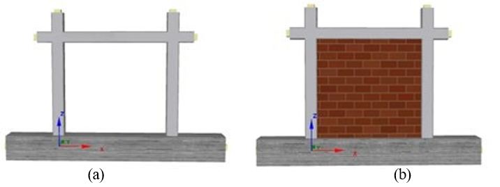
Figure 5: Show Shapes of Models in Seismostruct; (A) Bf, (B) If
Results and Discussion
In this section, the results of the eight models under investigation will be discussed. Results such as pushover analysis relations will be presented.
Effect of Infilled-Frame (IF)
Results are displayed pushover analysis of bare frame (BF) and infill-frame (IF). Figure 6 shows the capacity curves of the two structure models. The first is the bare frame model, where the peak load is 43.6 kN at a 2.64% drift ratio. The second is the masonry infilled frame model, where the infilled frame reached its first peak strength at 0.2% drift ratio and the post- peak strength at about 0.96% where the peak load was 115.7 kN. Using an infilled-frame increases peak load more than the bare frame. the stiffness of infilled frames is higher than bare frame structures.

Figure 6: The Capacity Curve of (BF), and (IF1)
Effect of Infill Panel Compressive Strength
Results are displayed pushover analysis of infill-frame (IF1), (IF2), and (IF3). Figure 7 shows the capacity curves of the three structure models. Infill frame model where infill panel compressive strength 7MPa (IF1), where the peak load is 115.7 kN at a 0.96% drift ratio, Infill frame model where infill panel compressive strength 11MPa (IF2), where the peak load is 136 kN at a 1.08% drift ratio, and Infill frame model where infill panel compressive strength 16MPa (IF3), where the peak load is 158 kN at a 0.96% drift ratio. increasing infill panel compressive strength that increases the load capacity of the infilled frame.

Figure 7: The Capacity Curve of (IF1), (IF2), and (IF3)
Effect of Infill Panel Thickness
Results are displayed pushover analysis of infill-frame (IF4), (IF5), (IF6), and (IF7). Figure 8 shows the capacity curves of the three structure models. Infill frame model where infill panel thickness 10mm (IF4), where the peak load is 108.4 kN at a 1.2% drift ratio, Infill frame model where infill panel thickness 12mm (IF5), where the peak load is 115.7 kN at a 0.96% drift ratio, Infill frame model where infill panel thickness 18mm (IF6), where the peak load is 115.7 kN at a 0.96% drift ratio, and Infill frame model where infill panel thickness 14mm (IF7), where the peak load is 132 kN at a 0.48 % drift ratio. increasing infill panel thickness that increases the load capacity of the infilled frame.

Figure 8: The Capacity Curve of (IF4), (IF5), (IF6), and (IF7)
Conclusion
The main aim of the research is to investigate the influence of unreinforced masonry infill walls, panel compressive strength, and panel thickness models under nonlinear pushover analysis were carried out using displacement controlled monotonic loading performance of R.C framed structure. Based on finite element analysis using SeismoStruct software and study of the results, the following conclusions were drawn:
• Infilled frames have higher stiffness than bare-frame structures.
• The peak load of the bare frame is 43.6 kN at a 2.64% drift ratio.
• The peak load of the infilled frame model reached its first peak strength at 0.2% drift ratio and the post-peak strength at about 0.96% where peak load was 115.7 kN.
• Increase infill panel thickness increases the capacity of the infilled frame against lateral loads.
• Increase infill panel compressive strength increases the capacity of the infilled frame against lateral loads.
• The peak load of the infilled-frame with compressive strength 7, 11, and 16 MPa is 115.7, 136, and158 kN respectively at a 0.96, 1.08, and 0.96 % drift ratio respectively.
• The peak load of the infilled-frame with infill panel thickness 10, 12, 18, and 24mm is 108.4, 115.7, 115.7, and132 kN respectively and at a 1.2, 0.96, 0.96, and 0.48% drift ratio respectively
References
- Jiang, H., Liu, X., & Mao, J. (2015). Full-scale experimental study on masonry infilled RC moment-resisting frames under cyclic loads. Engineering Structures, 91, 70-84.
- Santa-Maria, H., & Alcaino, P. (2011). Repair of in- plane shear damaged masonry walls with external FRP. Construction and Building Materials, 25(3), 1172-1180.
- Zhou, D., Lei, Z., & Wang, J. (2013). In-plane behavior ofseismically damaged masonry walls repaired with external
- Liu, H., & Hua, S. F. (2013). Test & analysis on seismic behaviors of brick walls retrofitted with post-tensioned tendons. Earthquake Resistant Engineering & Retrofitting, 49(1), 193-203.
- Kumbasaroglu, A., Yalciner, H., & Aydin, Y. F. (2017). The effect of infill wall frames on seismic performance levels of reinforced concrete buildings. In ICEDyn 2017: International conference on structural engineering dynamics, July (pp. 3-5).
- Nicola, T., Leandro, C., Guido, C., & Enrico, S. (2015). Masonry infilled frame structures: state-of-the-art review of numerical modelling. Earthquakes and structures, 8(3), 733-759.
- Khan, N. A., Monti, G., Nuti, C., & Vailati, M. (2021). Effects of infills in the seismic performances of an RC factory building in Pakistan. Buildings 2021, 11, 276.
- SeismoSoft, S. (2006). A computer program for static and dynamic nonlinear analysis of framed structures. Disponível online em: http://www. seismosoft. com.
- Basha, S. H., & Kaushik, H. B. (2019). A novel macromodel for prediction of shear failure in columns of masonry infilled RC frames under earthquake loading. Bulletin of Earthquake Engineering, 17, 2219-2244.
- Rodrigues, H., Varum, H., & Costa, A. (2010). Simplified macro-model for infill masonry panels. Journal of Earthquake Engineering, 14(3), 390-416.
- Crisafulli, F. J. (1997). Seismic behaviour of reinforcedconcrete structures with masonry infills.
- Abdelaziz, M. M., Gomaa, M. S., & El-Ghazaly, H. (2017). Effect of unreinforced masonry infill walls on seismic performance of reinforced concrete framed structures. The Open Civil Engineering Journal, 11(1).
- Council, B. S. S. (1997). NEHRP Commentary on the Guidelines for the Seismic Rehabilitation of Buildings(FEMA Publication 274). ATC-33 Project, Washington, DC.
- Smith, B. S. (1967). Methods for predicting the lateral stiffness and strength of multi-storey infilled frames. Building Science, 2(3), 247-257.
- Amato, G., Cavaleri, L., Fossetti, M., & Papia, M. (2008). Infilled frames: influence of vertical loads on the equivalent diagonal strut model. Procedings of 14th WCEE, Beijing, China. CD-ROM, Paper, 05-01.
- Manual, B. P. (1999). EVALUATION OF EARTHQUAKE DAMAGED CONCRETE AND MASONRY WALLBUILDINGS. Federal Emergency Management Agency, FEMA, 306.
- Mainstone, R. J. (1971). SUMMARY OF PAPER 7360. ON THE STIFFNESS AND STRENGTHS OF INFILLEDFRAMES. Proceedings of the Institution of Civil Engineers, 49(2), 230.
- Mainstone, R. J. (1974). Supplementary note on the stiffnesses and strengths of infilled frames. Building Research Establishment, Building Research Station.
- Bazan, E., and Meli, R., "Seismic analysis of structures with masonry walls," Proc. Proc., 7th World Conf. on Earthquake Engineering, International Association of Earthquake Engineering (IAEE) Tokyo, pp. 633-640.
- Hendry, A. W., & Hendry, A. W. (1998). Structural design ofmasonry buildings. Structural Masonry, 1-15.
- Tassios, T., "Masonry infill and R/C walls under cyclic actions," Proc. CIB Symposium on Wall Structure, InvitedState–of-the Art Report, Warsaw.
- Te-Chang, L., & Kwok-Hung, K. (1984). Nonlinear behaviour of non-integral infilled frames. Computers & structures, 18(3), 551-560.
- Decanini, L., and Fantin, G., 1986, "Models simplifications de la mampostería incluida en porticos," Caracteristicas de stiffness resistencia lateral en estado limited. Jornadas Argentina’s de Ingeniería Structural, 2, pp. 817-836.
- Paulay, T., & Priestley, M. N. (1992). Seismic design of reinforced concrete and masonry buildings (Vol. 768). New York: Wiley.
- Durrani, A. J., & Luo, Y. H. (1994). Seismic retrofit of flat- slab buildings with masonry infills. In Proceedings from the NCEER workshop on seismic response of masonry infills (pp. 1-8).
- Flanagan, R. D., & Bennett, R. M. (1999). Bidirectional behavior of structural clay tile infilled frames. Journal of structural engineering, 125(3), 236-244.
- Cavaleri, L., Fossetti, M., & Papia, M. (2005). Infilled frames: developments in the evaluation of cyclic behaviour under lateral loads. Structural Engineering and Mechanics, An Int'l Journal, 21(4), 469-494.
- Papia, M. A. U. R. I. Z. I. O., & Cavaleri, L. I. B. O. R. I.O. (2001). Effetto irrigidente dei tamponamenti nei telai inca. In Atti della 2 conferenza plenaria, Firenze (pp. 85-94).
- Sutherland, R. J. M. (1981). BRICK AND BLOCKMASONRY IN ENGINEERING. Proceedings of the Institution of civil Engineers, 70(1), 31-63.