
World Journal of Forest Research(WJFR)
ISSN: 2994-5569 | DOI: 10.33140/WJFR


Research Article - (2026) Volume 5, Issue 1
Level Measurement in Petrochemical Reactors Using Radiometric Gauge with Cobalt-60 Source
Received Date: Apr 18, 2025 / Accepted Date: Jun 24, 2025 / Published Date: Apr 02, 2026
Copyright: ©2026 Ycaro Souza de Jesus. This is an open-access article distributed under the terms of the Creative Commons Attribution License, which permits unrestricted use, distribution, and reproduction in any medium, provided the original author and source are credited.
Citation: de Jesus, Y. S. (2026). Level Measurement in Petrochemical Reactors Using Radiometric Gauge with Cobalt-60 Source. World J Forest Res, 5(1), 01-08.
Abstract
Level measurement, in the industrial context, involves monitoring liquid or solid contents to enable continuous process control such as buffering, mixing, dosing, or resistance management. Among the various technologies available, radiometric level measurement has become prominent for its reliability in challenging conditions like high temperatures, pressure, and abrasion. This paper presents a case study on maintaining measurement accuracy with a Cobalt-60 radiometric source after reaching its first half-life. It proposes a solution that prolongs source usability without compromising process safety, highlighting challenges and adjustments necessary in petrochemical reactors.
Keywords
Level Measurement, Radiation, Reactor, Radiometric Gauge
Introduction
In process control, the basic objective is to maintain a given variable at a desired value, even when it is subjected to external disturbances [1].
In all these processes, it is absolutely essential to control or maintain constant variations. The objective is to improve quality, reduce energy waste, increase the quantity produced and maintain safety. For example, we need to control pressure, flow, temperature, level, pH, conductivity, speed and humidity in many of these processes. Measurement and control instruments are elements that allow us to keep these variables under control [2].
Level is one of the most common and widely used variables in industrial applications. Level measurement is defined as the determination of the position of an interface between media, which can be liquids, solids or a combination of them. The interface can be between a liquid and a gas or vapor, two liquids, or between a solid and a gas [3].
Achieving the correct level reading in a petrochemical reactor is a critical process variable in maintaining a good operational process in the petrochemical industry. Since this reading can be used in safety integrity level (SIL) loops or in plant safety shutdowns due to high or low level, the level reading of the reader must be reliable [4].
Methods
Level sensors are used for the control of liquids or solid grains, contained in reservoirs, silos, open tanks, pressurized tanks in industry. They are useful in detecting a fixed level and in continuous measurement [5].
Due to the need to measure the level in different environments and in different types of liquids, granular solids or powder, there are a variety of level sensors available: capacitive, infrared, hydrostatic, ultrasonic, radar, laser, optical, displacer, among others [6].
The selection of the measuring system to be used should consider the application specifications, type of product whose level is to be measured, the desired accuracy, costs and other existing restrictions [3].
For level measurement in petrochemical reactors, after weighing all the pros and cons of each measuring technology, radiometric (nuclear) devices are selected 80% to 90% of the time, due to their reliability, when it comes to planning that includes variables with fluids that contain gases, vapors, foams, pressure, double phase, high simultaneous temperatures [4].
Radiometric level gauges, employing isotopes such as Cesium-137 or Cobalt-60, stand out for their non-contact measurement capabilities and immunity to harsh environmental conditions. However, the finite half-life of the radioactive source introduces challenges in sustaining measurement accuracy over time. This study explores a case where a Cobalt-60 source has reached its first half-life and proposes a practical solution to maintain reliable measurement without source replacement.
â?? Biographical notes: Ycaro Souza is a master's student in electrical engineering at the Federal University of Paraná, with electrical Engineering degree at Guararapes University. Automation engineer with experience in the areas of process control, measurement, instrumentation, automation in units, of pulp and paper, petrochemicals, oil and gas.
Process control through nuclear measurements is a non-contact measurement and is not affected by pressure, temperature or physical-chemical properties of the product. When in use, ionizing radiation does not affect the material being measured. Furthermore, in most cases, the systems are mounted externally to the vessel/pipe, thus avoiding the need to stop the process for their installation. Cesium-137 or Cobalt-60 sources are normally used, both of which emit gamma radiation [7].
One technology used in the measurement that is the subject of this work is a Cobalt-60 source. The operating principle of the radioactive sensor lies in the absorption of a radioactive beam by the product of which a certain characteristic is to be measured, in this case level. The source emits gamma rays, using Cobalt (60Co – half-life – 5.3 years) [8].
The particles emitted by the radioactive source pass through the reactor walls, the material contained therein and sensitize the detector. As the level rises, the material moves between the source and the detector, interfering with the trajectory of the particles. The reactor material then absorbs part of the energy, causing the intensity of the radiation perceived by the detector to decrease proportionally with the variations in the level [5].
As already indicated, the half-life (the time it takes for an isotope to lose half of its strength) of Cobalt 60 is 5.3 years. In a short period of time, the source would lose half of its radiation intensity and could compromise the level measurement, and this source could be exceeded after approximately five years. This fact would make the use of this measurement principle extremely expensive and bureaucratic [8].
The objective of this work is to propose a solution for measuring the level of a petrochemical reactor in which the radioactive source (Cobalt 60) has already reached its first half-life, without having to replace the source and the reliability of the process remains in safe conditions.
Case Study
A study was carried out in an application in petrochemical reactors that use radiometric level meters, whose cobalt 60 sources have reached their first half-life. The idea of the study was to conduct a prospection of continued use of the radioactive source and to predict actions to be taken to ensure continued indication of the radiation level without occasional disruptions to the process.
Lines A and B of the reactors of the petrochemical research unit use radioactive sources to enable level reading. The problem is that the radioactive sources of the project are cobalt 60, which have a half-life of 5.3 years.
The ideal solution to the problem would be to perform a fault in the transmitter of each vessel, however, in the design of the Petrochemical unit, there were no tools to prove the subsidies to calibrate the instruments.
The subsidies needed to prove the ideal solution would be:
I. Empty each vessel and ensure that they remain completely clean internally;
II. Open the upper manhole to leave the vessel atmospheric;
III. Install a hose on the side of the vessel and connect it to the base of the vessel to make a level indicator with the principle of communicating vessels;
IV. Fill the vessel with demineralized water to compare the radiation count decayed with the fluid inside the vessel with the indication of the level indicator of the communicating vessel. However, one of the problems that prevents the implementation of the ideal solution is that in the operational process of each vessel (reactor) a thermoplastic product is used at 300°C, which in the event of an attempt to drain the vessel for cleaning, leaves around 8% of residues in the vessel and as the temperature drops to drain, the residues of the product enter a molten state, solidifying inside each vessel, making cleaning impossible. Therefore, it is not possible to clean the vessel and leave it in a condition to apply the aforementioned solution.
Other alternatives were evaluated:
I. Using a solvent that heats the heat or the refuge of the vessel walls and would clean the vessel, however, we would need a unit to recover this solvent, since it is not possible to send the thermal solvent to the Effluent Treatment Plant, since the solvent would kill the anaerobic bacteria;
II. The acquisition of a new radioactive source of Cesium 137 or Cobalt 60, however, the bureaucracy involved in the acquisition and disposal of old radioactive sources makes this option not the most cost-effective.
Furthermore, the option for a Cesium 137 source, despite having a much longer half-life (30 years), would require the unit to be shut down for a long period, since the radioactive material in Cesium 137 would take up more physical space to emit the same radiation intensity required for ideal level measurement, so we would need a larger enclosure, and to make its installation feasible, many changes to the vessel structures would be necessary.
Therefore, once the premises raised above were considered, we sought an alternative through a case study, aiming to find a solution to the problem without the need to replace the source, ensuring level measurement within acceptable tolerances and errors.
The meters studied are installed in two identical production lines in a petrochemical plant, which operate in parallel and are called line A and line B. In each line, one meter is installed in a vertical vessel and two meters are installed in a horizontal vessel, with one meter installed at the inlet and the other at the outlet of the material in this vessel.
The meters are composed of the following components: Radioactive Source / Shielding: gamma ray emitter.
Detector: device sensitive to gamma radiation that converts the radiation into electrical pulses. Evaluation Unit: unit that receives the count of pulses generated by the detector and converts it into a material level value.

Figure 1: Basic Arrangement of Level Meter
The radioactive sources are made of Cobalt 60 and manufactured on 02/10/2011. Table 1 is presented below with the information and characteristics of each radioactive source:

Source: Berthold Instruments
Table 1: Radioactive Source Data

Figure 2: Illustrates the Shielding of the Radioactive Source Used
The detectors are model LB 5401-03, 50/50 crystal, with cooling and radial collimator.
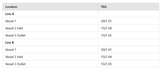
Table 2: Location and Tags of the Detectors
Figures 3, 4 and 5 below show the detectors mounted in line A
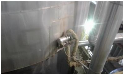
Figure 3: Photo of the A30LT-01 Detector

Figure 4: Photo of the A15LT-04 Detector
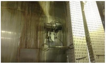
Figure 5: Photo of the A15LT-05 Detector
The evaluation units are installed in a panel at substation 500. They are model LB 440-02.

Figure 6: Front Photo of LB 440 Evaluation Units Installed on the Panel
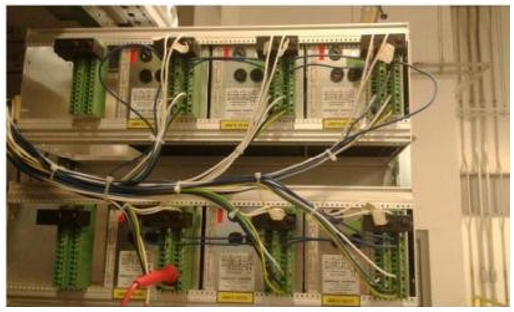
Figure 7: Rear Photo of LB 440 Evaluation Units Installed on the Panel
Time Constant: The two production lines, A and B, are identical from the physical construction of their components to the type of material used in production. Therefore, we expected similar configuration values for the meters of both lines. The time constant is one of the main parameters regarding measurement stability, since the evaluation unit calculates a moving average from the measurement values provided by the detector using a defined time constant. One of the characteristics of this type of meter is the use of a filter at its output to reduce the effects of statistical variation, since the radioactive source is not emitting gamma rays at a constant rate, this is a statistical process. According to the meter manual, to reduce statistical variations, you should select the largest time constant that is allowed in the process. Of course, this depends on the permissible error in the process during a maximum possible rate of change. Regarding the possibility of replacing radioactive sources, we gather all the information in the field and send it to the manufacturer.
According to him, radioactive sources must be exceeded when the total error in the measurement reaches the value that is especially harmful to the process. To calculate the total error, the following calculation is applied:

Where:
σ is the standard deviation
It is a pulse count in idle
τ is a time constant
Taking the B30LY-01 tag as an example, we have:
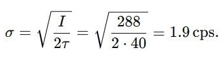
So, the effect due to the variation in background radiation is 2σ. With this, we calculate: Error on statistical decline, Error A = ±2σ / pulse variation from 100% to 0%. We calculate, Error A = (4 x 1.9) / (288-22), therefore Error A = 2.8% of the level. We need to calculate the error due to the effects on the detector of change in background radiation, Error B = ± 15% of the background radiation (for this detector) / pulse variation from 100% to 0%, therefore Error B = 4 / (288-22) Error B = 1.5% of the level.
So, we have Total error = √ (Error A² + Error B²), therefore Total error = √ (2.8² + 1.5²), Total error = 3.2% of the level. Based on this calculation, the errors below were calculated for all meters:

Table 4: Full Scale Error Calculated by Instrument
As time passes, the pulse count will be decreasing due to decay of source activity radioactive, so the error also increases. Therefore, to determine at what point the sources radioactive materials must be replaced, it must be checked which is the maximum acceptable measurement error for the process, as the From this and based on the calculation presented above, it can be calculated how long the radioactive sources can be used.Based on the calculated errors, we can state that all the meters in 2018 were measuring within the tolerance permissible for the process, which is +- 3% of the value full scale. However, due to the decline of activity of radioactive sources, the error of the measured value in Some meters will exceed the 3% value.
The error of the measured value meets the background error scale, only when the measurement reaches 100%. In the measured value error, the error will always be the same percentage of the actual measurement. Using as an example gauge of B30LY01 with measuring range is 1100mm, thus the full scale (100%) is 1100 mm, if the measurement is carried out at 100% of the level, the error will be the same as the full-scale value, in this case +- 33 mm. However, if measurement is carried out at 50% of the level, the error value will be of +- 16.5 mm, that is, half the error of the background value scale. Below we have Figure 8 with the behavior of the % of error of full-scale value vs error of measured value depending on the measuring range:

Figure 8: Full Scale Error Curve
In the applications of level gauges installed in vessels with Cobalt 60 (Co-60) radioactive sources, the half-life is of 5.3 years, calculated according to the formula and graphs in Figure 9 below:

Figure 9: Half-life Calculation Graph and Formula
Conclusion
For the meter to have an error of less than 3% throughout measuring range within the conditional assumptions, there is a following technical option for this:Detector replacement: The detector must be replaced with a detector with greater sensitivity, but without losing the stability of measurement. We study current technologies, manufacturers of transmitter/source, where the supplier market has the SuperSens detector, whose scintillation crystal is larger than the of the currently installed detector. The installed detector has the crystal with dimensions (diameter and length) of 50x50 mm, while the SuperSens has dimensions of 150x150 mm. This makes the pulse count per second increase considerably, which allows us to use a radioactive source for at least another half-life. Considering the example calculated for TAG B30LY-01 we will have: The empty pulse count is approximately 864, so σ= 2.93 cps. The effect due to the variation in background radiation is 2σ. With this, we calculate: Error about the decline statistical, Error A = ±2σ / pulse variation from 100% to 0%. We calculate, Error A = (4 x 2.93) / (864-66), Error A = 1.47 % of level. we need to calculate the error due to the effects on detector of change in background radiation, Error B = ± 15% of background radiation (for this detector) / pulse variation from 100% to 0%, so Error B = 10/ (574-66) Error B = 1.25% of the level. So we have Total error = √ (Error A²+Error B²), therefore Total error = √ (1.47²+1.25²), Total error = 1.93% of level.
Replacing the detector would avoid procedures bureaucratic and costs related to acquisition, transportation and installation of radioactive sources, as well as procedures and costs related to source disposal current. In our assessment, the best option was to replace the detector/transmitter, as we would be able to apply this solution, extend the use of the source for another 5.3 years, in media. In addition to being able to carry out the experience based on the original confidence curves. Investment: To replace the 6 transmitter detectors of line A/B we would need to invest approximately US$ 220,830.00 [9-11].
References
- Franchi, M.C. (2015). Instrumentação de processos industriais. 1 ed. São Paulo: Érica.
- Eletrobras (2008). Instrumentação e controle: guia básico. Brasília: IEL/NC.
- Bega, E. (2006). Instrumentação Industrial. 2 ed. Rio de Janeiro: Interciência: IBP.
- Almas, A. Overcome Challenges of Correct Level Reading in a Petrochemical Reactor.
- ALBUQUERQUE, P. U. B. D., & THOMAZINI, D. (2005).Sensores industriais: fundamentos e aplicações. São Paulo: Érica.
- Souza, M. O. (2018). Sensor de nível tipo deslocador com autocompensação da densidade do líquido.
- Führ, J. C. (2012). Avaliação de um plano de proteção radiológica de uma indústria química.
- Fialho, A. B. (2002). Instrumentação industrial: conceitos, aplicações e análises. Saraiva Educação SA.
- https://instrumentos-lince.com.br/o-que-e-medicao-de-nivel/, 30/09/2020.
- Cassiolato, C. (2005). Medição de nível & nível de interface.Revista Controle & Instrumentação, 110(3), 27-35.
- Lince, A. (2020). Tecnologia para Medição de Nível ideal para os processos mais desafiadores.