
Journal of Agriculture and Horticulture Research(JAHR)
ISSN: 2643-671X | DOI: 10.33140/JAHR
Impact Factor: 1.12

Research Article - (2026) Volume 9, Issue 2
Justification of Parameters and Operating Modes Rotary Cultivator for Potato Plantings
Received Date: Oct 15, 2026 / Accepted Date: May 01, 2026 / Published Date: May 18, 2026
Copyright: ©2026 Pervushin V F, et al. This is an open-access article distributed under the terms of the Creative Commons Attribution License, which permits unrestricted use, distribution, and reproduction in any medium, provided the original author and source are credited.
Citation: Pervushin, V. F., Salimzyanov, M. Z., Casimov, N. G., Shmykov, S. N., Costin, A. V. (2026). Justification of Parameters and Operating Modes Rotary Cultivator for Potato Plantings. J Agri Horti Res, 9(2), 01-11.
Abstract
The article presents the results of theoretical research in the field of kinematics of interaction of rotary working elements with the soil at the moment of contact with the soil.
Keywords
Technology, Harrow, Ridge, Tuber, Root Collar, Rotary Cultivator
Introduction
To study the process of interaction of the working elements of the harrow with the soil. The founder of agricultural mechanics, Aca-demician V.P. Goryachkin, established that achieving high quality indicators of working parts is possible only with optimal geometric and kinematic parameters and dynamic operating mode. The working parts of passive working parts move along a straight line, so their soil loosening intensity is low. Active (rotary) working parts best meet the agronomic requirements of soil loosening and weed control. The increased interaction with the soil, and therefore the soil loosening intensity of rotary working parts, is largely determined by the type of their movement. According to our working hypothesis, a rotary working tool, rolling along the surface of a ridge and adjacent to it, can comb and drag weeds along the ridge, break the connection between their root collars and the soil, and also dump them into the inter-row space. Such functionality for the envisaged technological process could be achieved by a rotary harrow that conforms to the ridge profile and passively rolls on the circumference of the lugs, the points of which describe the trajectory of an ordinary cycloid.
A rotary harrow is a geometric figure made up of two truncated cones and a cylinder, onto the surface of which fingers or scraper bars can be welded. The geometric parameters of the rotary harrow design are determined by the dimensions of the ridge profile, the spacing between plant rows, the depth of the tubers, and the parameters of the serial cultivator on which the rotary working element is planned to be installed and adjusted. Theoretically, the ridge profile can be taken in the form of a trapezoid, which is characterized by a height h , a width b of the upper base and the width B of the lower base, equal to the row spacing . In this case, we can write that the harrow width, H, considering the width of the grip of the arrow paw will be equal to: H = B – a, According to the Research Institute of Crop Protection, the comb parameters before leaving had the following values, given in Table 1.
|
Indicators |
Values, cm |
|
1. Height |
12…16 |
|
2. Width at base |
70 |
|
3. Width at the top |
5…10 |
Table 1: Ridge Parameters for Potato Planting
In addition, when justifying the geometric parameters of the har-row, it is necessary to consider:
• That the larger the diameter of the harrow along the lugs, the less force is required to roll it;
• To achieve the effect of combing out weeds, it is necessary that the kinematic operating mode indicator ![]() < 1.
< 1.
Absolute Trajectory of Motion, Speed and Acceleration Working Elements of a Rotary Harrow
The main distinguishing feature of rotary tillage machines and im- plements is the rotational motion of their working elements. When rotation is transmitted from the engine to the rotor via the drive-shaft, the rotor becomes active (active rotary working elements).If the working element is rotated by passive interaction with the soil under the tractor's traction force, it is classified as a passive rotary working element. The intensity of the technological oper-ation performed by rotary working elements largely depends on their rotational speed and the type of movement of the working elements. In recent years, much attention has been paid to the development and use of machines with rotary working bodies for inter-row cultivation of row crops, which have very significant advantages over passive working bodies. Theoretical studies of ro-tary working elements have been carried out in sufficient detail in [6.8]. However, to date, the patterns of formation of the trajectories of motion and moments of forces acting on the working elements of a rotary drum rolling with the surface of the ridge, depending on the kinematic operating mode indicator, have not been theoretical- ly investigated or identified:
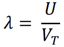
where U is the linear speed of the harrow points,
VT - forward speed of the tractor. The study of the patterns of change in the nature of the trajectories of the working elements of a rotary harrow and the formation of moments of force allows us to analyze the technological process of the harrow. The trajectory of any point of the working elements of a rotary harrow is a cycloid (Figure 1), which is the result of their rotation around the axis of the harrow at a speed of U = ![]() ri (ri is the radius of rotation of the initial points of the working elements,
ri (ri is the radius of rotation of the initial points of the working elements, ![]() is the angular velocity of the harrow) and translational movement with the tractor at a speed of VT. t .
is the angular velocity of the harrow) and translational movement with the tractor at a speed of VT. t .

Figure 1: Absolute Trajectory of the Rotary Harrow's Initial Points When Rolling along the Lug Rim
The trajectory of any point lying on the harrow surface in a system of fixed coordinates, is described in parametric form by equations:
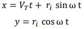
where t is time.
In our case, all points of the harrow surface located on the smaller radius of the lug rim have a kinematic operating mode index ![]() < 1 and follow a trajectory of movement in the form of a shortened cycloid.
< 1 and follow a trajectory of movement in the form of a shortened cycloid.
Theoretically, three possible harrow rolling patterns are possible:
1. Along the circumference of the cylindrical section;
2. Along the circumference of the conical section;
3. Along the circumference of the lug rim.
In the first case, all points lying on the cylindrical part of the harrow describe a normal cycloid and the kinematic operating mode index ![]() = 1. All other points of the harrow lying on large radii describe elongated cycloids and their kinematic operating mode index
= 1. All other points of the harrow lying on large radii describe elongated cycloids and their kinematic operating mode index ![]() >1 (Figure 2).
>1 (Figure 2).

Figure 2: Rolling of the Harrow on the Circumference of the Cylindrical Part of the Harrow
In the second case, when the harrow rolls along the conical part, all the points of the harrow lying on the smaller radius will describe a shortened cycloid (elongated) and their kinematic operating mode index ![]() <1, and the points lying on the larger radius will describe an elongated cycloid and have kinematic operating mode indexes
<1, and the points lying on the larger radius will describe an elongated cycloid and have kinematic operating mode indexes ![]() >1 (Figure 3).
>1 (Figure 3).

Figure 3: Rolling of the Harrow on the Circumference of the Conical Part of the Harrow
In the third case, when the harrow rolls along the rim of the lugs, all the points of the harrow lying on the smaller radius describe a shortened cycloid (elongated) and their kinematic operating mode index ![]() is <1. The points lying on the larger radius describe a shortened cycloid (elongated) and their kinematic operating mode index
is <1. The points lying on the larger radius describe a shortened cycloid (elongated) and their kinematic operating mode index ![]() is <1 (Figure 4).
is <1 (Figure 4).

Figure 4: Rolling of the Harrow along the Circumference of the Lug Rim
Theoretically, the third option is the most favorable and effective, in which the points located on the smaller radius of the harrow make shortened (elongated) cycloids and at the same time the working elements of the harrow drag the upper surface layer of soil forward, destroying weeds in the white thread phase. The speed and acceleration of the harrow's scraper bars during contact with the soil play a key role in the intensity of the soil loosening and weed control operations performed by a rotary harrow (Figure 5).
The absolute speed of the characteristic points of the harrow scrap-er bar is written as:
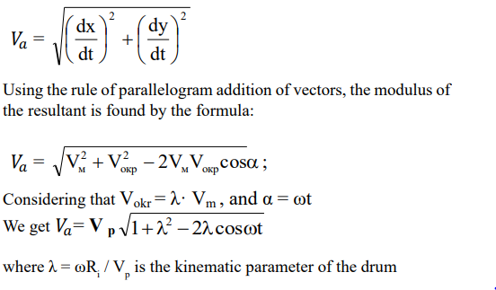

Figure 5: Trajectory and Speed of the Scraper Bar during its Contact with the Soil
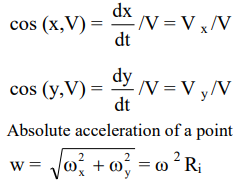
The direction of the velocity vector V in space is determined by the direction cosines.
To achieve the intended technological process of pulling the top-soil and weeds, along with the root collar, into the row spacing, the rotary harrow must roll without slipping along the lug rim and de-scribe a regular cycloid. In this case, all other points on the harrow lying outside the harrow rim circumference, such as the lug points, will describe an elongated cycloid and have a kinematic operating mode index of ![]() > 1, while all points lying inside the harrow rim circumference (points on the tines and scraper bars) will describe a shortened cycloid and have a kinematic operating mode index of
> 1, while all points lying inside the harrow rim circumference (points on the tines and scraper bars) will describe a shortened cycloid and have a kinematic operating mode index of ![]() < 1.
< 1.
Study of Translational Motion Scraper Bar in the Contact Zone with the Soil
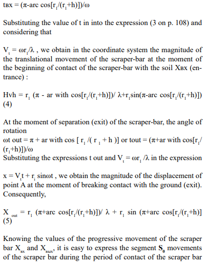
Of practical interest is the process of interaction between the scraper bar and the soil and its behavior in the contact zone. To do this, we will examine the kinematics of the scraper-soil interaction during the scraper-soil contact period. We will analyze the seg-ment of the path from the beginning of the scraper-soil contact (the beginning of the surface soil layer being pulled through) at point 0 to the end of the contact (the end of the surface soil layer being pulled through) at point 6, along which weeds are combed out, the soil crust is loosened, and the soil crust is broken down (Figure 6).

Figure 6: To Determine the Segment S0 of the Progressive Movement of the Scraper Bar or Finger in the Zone of its Contact with the Soil
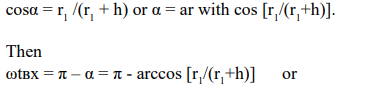
Graphical plotting of the trajectory and its analysis clearly demon-strate that the scraper bar enters the soil at an acute angle when it first contacts the soil, assumes a vertical position midway through the stroke, and leaves the soil surface at an obtuse angle at the end of the stroke. Thus, during the first half of the stroke, the scraper picks up soil and weeds, and during the second half, it drags them through and releases them, which greatly facilitates the process of dragging weeds and loosening the soil. When the drum is rolling, an important role is played by the trajectory of movement described by the scraper during its contact with the soil, limited by a certain arc (0-6) (Figure 6) and determined by the beginning of the scraper's entry into the ridge at point 0 and the end of its working stroke at point 6, on the line of which weeds are combed out, the soil crust is loosened and destroyed. Arc 0-6 of the scraper-bar trajectory corresponds to a segment of size So progressive movement of the harrow.Let us analyze the section of the harrow's path from the moment the scraper-bar begins to contact the soil (the beginning of dragging the surface layer of soil) at point 0 and the end of contact with the soil (the end of dragging the surface layer of soil) at point 6. From
Figure 6 we find that at the moment of the beginning of contact of the scraper-bar with the soil, its coordinate y takes on a value equal to r1. Therefore
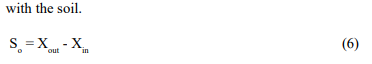
The results of solving the components of equations (4) and (5) are presented in Table 2
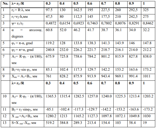
Table 2: Results of Solving the Components of Equations (4) and (5) for Points with the Kinematic Operating Mode Indicator ![]() =r2/R in the range from 0.3 to 1.0
=r2/R in the range from 0.3 to 1.0
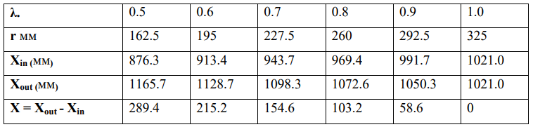
Table 3: Results of Solving Equations (4) and (5) for Kinematic Operating Mode Indicators ![]()
from 0.5 to 1.0

Figure 7: Dependence of the Working Stroke S0 on the Kinematic Operating Mode Indicator ![]()
Study of the Speed of the Working Element in the Zone of its Contact with the Soil
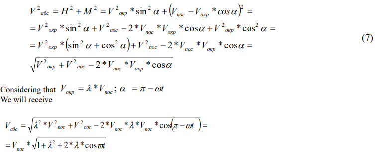
Absolute speed is one of the most important performance charac- teristics of rotary tillage machines and implements. It is equal to the geometric sum of the circumferential and forward speeds.
![]()
Using the rule of parallelogram addition of vectors and the Pythag-orean theorem, the modulus of the resultant can be found in the following sequence (Figure 8 a and b).
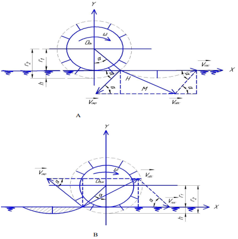
Figure 8: To Determine the Absolute Speed of the Scraper Bar: a) At the Moment of Entering the Soil; b) At the Moment of Exiting the Soil
In the middle position, the absolute speed is equal to the difference between the translational speed and the peripheral speed, since they lie on the same line and are directed in opposite directions (Figure 9).
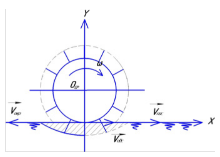
Figure 9: Determining the Absolute Speed of the Scraper Bar in the Middle Position
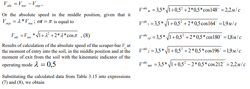

Figure 10: Dependence of Absolute Speed on the Working Stroke Va and the Kinematic Operating Mode Indicator ![]()
Study of Acceleration of a Working Element in its Contact Zone with the Soil
Acceleration is defined as the derivative of absolute velocity with respect to time. Acceleration at the moment of entering and exiting the soil
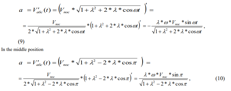
Results of calculating the acceleration of the scraper-bar ![]() at the moment of entering the soil, in the middle position and at the moment of exiting the soil with the kinematic indicator of the operating mode
at the moment of entering the soil, in the middle position and at the moment of exiting the soil with the kinematic indicator of the operating mode ![]() = 0,5. Substituting the calculated data from Table 3 into expressions (9 and 10), we obtain:
= 0,5. Substituting the calculated data from Table 3 into expressions (9 and 10), we obtain:
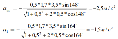
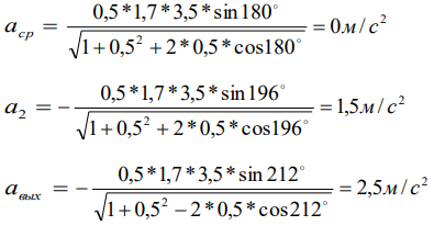
Based on the results of solving the equations, the following graph-ical dependencies of the acceleration of a the scraper-bar point on the working stroke S0 and the kinematic operating mode indicator were obtained (Figure 11).

Figure 11: Dependence of Acceleration α on the working stroke α and the kinematic operating mode indicator λ
Conclusion
Graph-analytical studies of a rotary harrow have shown that the harrow's scraper bar is positioned at an acute angle when it first contacts the soil, assumes a vertical position midway through the stroke, and leaves the soil surface at an obtuse angle at the end of the stroke. Thus, during the first half of the stroke, the scrap¬er bars collect soil and weeds, and during the second half, they drag them through and release them. 2. The speed and acceler¬ation of the scraper bar in the contact zone with the soil were calculated for the kinematic operating mode index λ = 0.5 at the beginning of contact with the soil, in the middle position and at the moment of separation from the soil surface, respectively:
References
- Pervushin, V. F., Levshin, A. G., Salimzyanov, M. Z., Kasimov, N. G., Shamaev, E. V., & Lebedev, I. Yu. (2015). Classification of rotating working bodies of agricultural machinery. Bulletin of the Izhevsk State Agricultural Academy, (3), 38-43.
- Pervushin, V. F., Medvedev, V. G., Salimzyanov, M. Z., & Kasimov, N. G. (2004). Features of improved technology of potato cultivation in Udmurtia. Potatoes and Vegetables, (1), 19-21.
- Patent 179170 Russian Federation IPC A01B 49/02. Combined tillage device : No. 2017144378: declared 12/18/2017: published 05/03/2018 / Pervushin V.F. applicant and patent holder Izhevsk State Agricultural Academy. - 3c: ill.
- Pervushin, V. F., Salimzyanov, M. Z., Fatykhov, I. Sh., & Ab-dullin, F. M. (2010). Rotary ripper.
- Pervushin, V. F., Salimzyanov, M. Z., & Fatykhov, I. Sh. (2013). Cultivator for care of potato plants.
- Pervushin, V. F., Salimzyanov, M. Z., & Nikolaev, V. A. (2009). Kinematic parameters of a rotary ripper. Mechanization and electrification of agriculture, (6), 37-38.
- Pervushin, V. F. (2011). Improving the efficiency of mecha-nized potato cultivation technology in small-scale farming.
- Pervushin, V. F. (2006). Conditions for rolling a rotary potato harrow without slipping. Mechanization and electrification of agriculture, (7), 10-11.
- Pervushin, V. F., Salimzyanov, M. Z., & Kasimov, N. G.(2011). Improved technology of potato cultivation in farms and personal subsidiary plots. Agricultural machinery, (4), 29-31.
- Pervushin, V. F. (1998). Towards substantiation of the design scheme of a haulm harvesting machine. In Proceedings of the scientific and practical conference of the Izhevsk State Agricultural Academy (pp. 39-40).
- Pervushin, V. F., Salimzyanov, M. Z., Kasimov, N. G., & Iva-nov, A. G. (2010). Increasing the level of mechanization of potato production in small-scale farming (farm and personal subsidiary plots). In Actual problems of agricultural mechanization (pp. 70-76).
- Pervushin, V. F., Salimzyanov, M. Z., Kasimov, N. G., Shamaev, E. V., & Lebedev, I. Yu. (2015). Application of fiber-glass rods in potato harvester elevators. Bulletin of the Izhevsk State Agricultural Academy, (3), 43-47.