
Journal of Geology & Mining(JGM)
ISSN: 3066-4950 | DOI: 10.33140/JGM


Research Article - (2024) Volume 1, Issue 1
Innovative Polymerized Sulfur-Based Composite Material for Underground Storage of Hydrogen
2Associate Professor, College of Natural and Health, Sciences, Zayed University, Abu Dhabi, UAE
Received Date: Nov 08, 2024 / Accepted Date: Dec 26, 2024 / Published Date: Dec 31, 2024
Copyright: ©©2024 Abdel-Mohsen O. Mohamed, et al. This is an open-access article distributed under the terms of the Creative Commons Attribution License, which permits unrestricted use, distribution, and reproduction in any medium, provided the original author and source are credited.
Citation: Mohamed, A. M. O., El Gamal, M. (2024). Innovative Polymerized Sulfur-Based Composite Material for Underground Storage of Hydrogen. J Geol Min, 1(1), 01-15.
Abstract
Underground energy storage in high-pressurized lined rock caverns is emerging as a viable solution for storing large volumes of energy in the form of pressurized gases, such as hydrogen and natural gas. This technology is particularly advantageous due to its potential to ensure the containment of gases with high specific energy in shallow rock formations, while operating under ambient temperature conditions. This paper (a) investigates the development of a novel polymerized sulfur-based composite material (PSCM) made of recyclable materials from oil and gas production industry (i.e., elemental sulfur) and steel manufacturing (i.e., Ladle-Furnace Slag (LFS) and Ground Granulated Blast Furnace Slag (GGBFS)); and (b) optimizes the composite proportions within the formed PSCM to enhance its physico-mechanical properties, such as packing density, compressive strength, and splitting tensile strength, for use to store hydrogen in high-pressurized underground lined rock caverns.
Through an experimental design guided by statistical analysis using Minitab-17 software, various compositions were mixed and tested to identify the optimal PSCM mixture ratios. The findings revealed that maximum compressive strength, reaching up to 58 MPa, and splitting tensile strength of 3.56 MPa were achieved with a mixture containing 34% polymerized sulfur, 36% dune sand, 19% LFS, and 17% GGBFS. The study also confirmed that better aggregate packing reduces voids, thereby minimizing the amount of polymerized sulfur required to fill these voids and increasing the overall strength of the PSCM. These results underscore the potential of PSCM as a sustainable and durable alternative to Portland cement concrete used as a liner material in constructing underground man-made caverns for hydrogen storage.
Keywords
Polymerized Sulfur, Aggregates, Fillers, Statistical Optimization, Packing Density, Compressive Strength, Splitting Tensile Strength, Hydrogen Storage, Shallow Rock Formations
Introduction
The construction of Lined Rock Caverns (LRCs) begins with the careful selection and excavation of a suitable rock formation [1-7]. The chosen site typically involves rock types with low permeability, such as granite, limestone, or other hard rocks, which offer natural resistance to gas migration. The excavation process includes drilling, blasting, and removing rock to create a cavern of the desired dimensions. The key steps in excavation are [8-11]:
1) the site selection whereby detailed geological surveys are conducted to identify areas with suitable rock properties, including strength, stability, and impermeability.
2) the drilling and blasting whereby precision drilling and controlled blasting are used to excavate the cavern, ensuring minimal disturbance to the surrounding rock.
3) the rock removal of the excavated materials out of the cavern, and the walls and ceiling are smoothed to prepare for lining installation.
Once the cavern has been excavated, the next critical step is the installation of a lining system. The primary purpose of the lining is to create an impermeable barrier that prevents the stored gas from leaking into the surrounding rock and to reinforce the cavern walls against the mechanical stresses induced by high-pressure storage. The lining materials are selected based on the type of gas being stored, the expected pressure levels, and the geological conditions of the site. The common lining materials include [8,10-13]:
a) Steel Liners: Which are commonly used due to their high tensile strength and ability to withstand significant internal pressures. They provide a robust barrier against gas leakage and can be fabricated into various shapes to fit the cavern's geometry. Steel linings are typically welded or bolted together to ensure a continuous, gas-tight seal;
b) Concrete Linings: Which are often used in combination with steel or as a standalone lining material, particularly in caverns where structural reinforcement is required. High-performance concrete mixes are designed to resist cracking and withstand the compressive forces exerted by the rock and the pressurized gas. Concrete linings may also incorporate additives or coatings to enhance their impermeability; and
c) Composite Materials: Such as polymerized sulfur composite material (PSCM) and synthetic polymers (SP). These materials offer a combination of high strength, low weight, and chemical resistance. PSCM and SP are particularly beneficial in environments where corrosion resistance is critical, such as in hydrogen storage.
Installation of lining systems involves three steps. The first is the surface preparation where the cavern walls are cleaned and smoothed to provide a uniform surface for the lining. This may involve applying a bonding agent to improve adhesion between the rock and the lining material. Second, the lining material is applied or installed in layers, depending on the design requirements. For steel linings, this may involve welding sections of steel plates together, while concrete linings are typically poured in place or applied using shotcrete techniques. Finally, after installation, the lining is sealed at all joints and interfaces to ensure complete impermeability. Pressure tests are conducted to verify the integrity of the lining and to identify any potential leaks or weaknesses.
The hydrogen permeability of some selected lining materials is shown in Table 1 [14-16]. Based on these permeability values, Gajda and Lutynski [17] estimated that during 60 days of hydrogen storage in a tank with 1000 m2 of inner surface, with 1 cm thick sealing liner and gas pressure of 1.0 MPa, at ambient temperature (20oC), approximately 1, 10,000, and 1,000,000 m3 STP of hydrogen will diffuse from the reservoir with lining materials of synthetic polymers, porous rock, and concrete, respectively. Therefore, synthetic polymers lining materials can be successfully used as a substitution for stainless steel.
|
Lining Material Type |
Permeability (m/sec) |
Lining Material Type |
Permeability (m/sec) |
|
Concrete |
7.804×10⁻⁷ |
Polymerized sulfur composite materials (average estimated by the authors) |
10-12 - 10-10 |
|
Concrete (average reported by the authors) |
(10−10 - 10-8) |
Epoxy resin |
1.820 × 10⁻¹³ |
|
Polymer–concrete |
3.414 × 10⁻⁷ |
Epoxy resin + graphite (5% vol.) |
2.350 × 10⁻¹³ |
|
Mudstone (Carbon) |
2.330 × 10⁻⁹ |
Epoxy resin + halloysite (5% vol.) |
3.220 × 10⁻¹³ |
|
Salt rock (Permian) (before creep) |
4.815 × 10⁻⁹ |
Epoxy resin + fly ash (5% vol.) |
1.770 × 10⁻¹³ |
|
Salt rock (Permian) (after creep) |
1.95 × 10⁻¹³ |
Epoxy resin + fly ash (30% vol.) |
1.774 × 10⁻¹³ |
|
Polyester resin |
2.611 × 10⁻¹³ |
Epoxy resin + fly ash (30% vol.) |
1.774 × 10⁻¹³ |
|
Polyurethane |
2.611 × 10⁻¹³ |
Stainless steel |
4.640 × 10⁻¹⁹ |
Table 1: Hydrogen permeability of some selected lining materials
In addition to providing a barrier against gas leakage, the lining system must also resist the mechanical stresses induced by the high-pressure gas stored within the cavern [13, 18]. These stresses include both internal pressure from the gas and external pressure from the surrounding rock formation. The mechanical stresses of prime importance are internal and external pressures as well as thermal stresses. The stored gas exerts significant internal pressure on the cavern walls, which can cause deformation or failure if the lining is not adequately reinforced; hence, the lining material must be strong enough to resist this pressure without cracking or rupturing. The weight and pressure of the overlying rock layers exert external pressure on the cavern walls, which can lead to compression or collapse if not properly managed; hence the lining system must be designed to distribute these pressures evenly and prevent localized stress concentrations. Finally, depending on the type of gas and the storage conditions, temperature variations can induce thermal stresses in the lining material. For example, the expansion and contraction of the lining due to temperature changes can cause fatigue and potential failure over time; hence, materials with low thermal expansion coefficients and high thermal stability are preferred to mitigate these effects.
Moreover, the long-term performance of the LRC depends on the durability of the lining system and the ability to maintain its integrity over the life of the storage facility [13]. Regular inspections and maintenance are essential to ensure that the lining continues to provide an effective barrier against gas leakage and resists the mechanical stresses of high-pressure storage. The durability factors that are of interest are resistance to corrosion, prevention of cracks and advanced monitoring systems [10, 19-21]. In the case of steel linings, corrosion is a significant concern, particularly in environments with moisture or corrosive gases. Protective coatings and cathodic protection systems are often used to prevent corrosion and extend the life of the lining [22,23]. Also, concrete linings are susceptible to cracking due to the combined effects of pressure, temperature changes, and chemical interactions with the stored gas [24]. Additives and reinforcement techniques are used to minimize the risk of cracking and to repair any damage that occurs over time [25]. Advanced monitoring systems, including sensors embedded in the lining, are used to detect changes in pressure, temperature, and structural integrity. These systems provide real-time data that can be used to identify potential issues before they lead to failure.
Therefore, the construction and operation of LRCs involve a combination of geological expertise, advanced materials science, and precise engineering to ensure the safe and efficient storage of pressurized gases. The choice of lining materials and the design of the cavern are critical factors that determine the success of the storage system, particularly in maintaining containment and resisting mechanical stresses over the long term.
Polymerized sulfur composite material (PSCM) has gained high consideration and attention because of its sustainable production and low environmental impact, which makes it an attractive construction material [26]. The interest in sulfur and its properties has been heading in two directions. The first concentrated on sulfur bonds, mastics, and concrete based on sulfur as a thermoplastic bonding material. Whilst, the second was devoted to the use of melted polymerized sulfur, for cement concrete manufacturers, to enhance the physical and mechanical properties of concrete products as well as to increase its resistance to corrosive environments [27]. The properties, as well as the application of PSCM, have been investigated in previous works [28-30]. This study supports and helps to increase awareness about using PSCM as a potential sustainable material in the construction industry for underground hydrogen storage.
PSCM is a thermoplastic mixture fabricated through the hot mixing of polymerized sulfur with mineral aggregates. When the molten polymerized sulfur cools down it solidifies, and the mix gains its strength. The process of PSCM manufacturing is based on “hot” technology where all the mixed ingredients are heated during the mixing process to reach a temperature in the range of 140- 150ºC. The specific amounts of all ingredients must be carefully optimized according to known practical criteria in addition to the desired mechanical and physical properties to be reached [26]. The evaluation of the effect of the various proportions of polymerized sulfur, aggregates, and fillers on the physico-mechanical properties of PSCM is somewhat difficult because of the mutual interactions between the variety of ingredients in the system. To this end, this study provides an experimental design, based on the statistical analysis, to obtain regions of optimal proportions of the mixing components in the material to be produced that attain the desired maximum mechanical properties that are expected in storing hydrogen in man-made LRCs.
In this study, samples of different PSCM compositions are produced and evaluated to select those with the desired maximum mechanical properties. This is a continuation of the author's previous studies on the PSCM formulations [26, 29-33]. It describes the application of a statistical experiment mixture design to optimize the properties of the newly developed PSCM. It enables logical inputs in terms of the proportions of the mixture components and the targeted responses/outputs in terms of bulk density, compressive, and splitting tensile strength. The studied PSCM mixture is composed of polymerized sulfur as a binder, dune sand, and alkaline solid waste products (i.e., Ladle-Furnace Slag, LFS) as an aggregate, and Granulated Ground Blast Furnace Slag, GGFBS, as a filler).Experiments with different compositions were prepared and tested to obtain the proper mix design that maximizes the physico properties of the produced mix.
Materials
Four feed materials for the PSCM mixtures were collected, locally, from the United Arab Emirates (UAE) as follows. The granular elemental sulfur with a purity of 99.9% was collected from the Al Ruwais refinery and is used to make the polymerized sulfur using the methodology presented in [29]. Dune sand was collected from a sandy hump in the Al Ain area, UAE. Ladle-Furnace Slag (LFS) waste material, a byproduct from the electric arc furnace process, was collected from Emirates Steel Factory in Abu Dhabi, UAE. Finally, the Ground Granulated Blast Furnace Slag (GGBFS) was collected from the Al Sharjah Cement Factory, UAE. Additional information regarding these materials can be found in [32].
Table 2 gives the main physical and chemical characteristics of the four materials. Figure 1(a-c) displays images of the used materials taken by the Scanning Electron Microscope (SEM). Sand is mainly composed of round and irregular particles with smooth surfaces, while LFS particles have rough surface texture, which includes high surface micro-pores, whereas GGBFS is composed of smooth angular particles. The X-ray diffraction (XRD) analysis of the main aggregates indicated the following: desert sand is mainly composed of quartz mineral SiO2, calcite CaCO3, and dolomite CaMg (CO3)2; the LFS is composed of Ca, Si, and Al oxides, wollastonite (βCaO·SiO2), anorthite CaO·Al2O3·2SiO2, CaS and αAl2O3; and the GGBFS is mainly amorphous calcium aluminum silicate and larnite (calcium silicate).
|
Properties/Composition |
Sand |
LFS |
GGBFS |
|
Color |
Yellowish red |
Faint gray |
Whitish |
|
Specific Gravity |
1.69 |
3.30 |
2.86 |
|
BET Surface Area(m2/g) |
5.61 |
2.38 |
5.92 |
|
% wt. of SiO2 |
76.4 |
30.29 |
33.12 |
|
% wt. of Fe (total) |
0.676 |
3.42 |
0.48 |
|
% wt. of Al2O3 |
0.47 |
10.12 |
16.27 |
|
% wt. of CaO |
16.35 |
51.12 |
41.12 |
|
% wt. of MgO |
2.158 |
4.33 |
7.5 |
|
% wt. of MnO |
0.05 |
0.50 |
0.191 |
|
% wt. of K2O |
1.13 |
0.03 |
0.362 |
|
% wt. of Na2O |
2.1 |
0.01 |
0.064 |
Table 2: Physical properties, and by-weight chemical composition of sand, Ladle-Furnace Slag (LFS), and Ground Granulated Blast Furnace Slag (GGBFS)
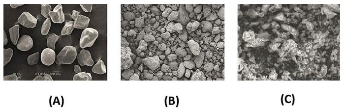
Figure 1: SEM analysis for (a) desert sand, (b) Ladle-Furnace Slag (LFS), and (c) Ground Granulated Blast Furnace Slag (GGBFS).
Production of Polymerized Sulfur Composite Material (PSCM)
The PSC mixtures were prepared according to the procedure, ACI 548.2R-93 [34] “mixing and placing of the sulfur concrete”. Since the mixing process is detailed in [33], only a brief description is given below.
1) Modify elemental sulfur by mixing it with an organic material (natural bitumen) (2.5%, by weight) to form the polymerized sulfur. In that mixing process, an emulsifying (blending) agent was used to enable uniform compatibility between elemental sulfur and the natural bitumen [29]. The reaction progress is tracked by visually observing the changes in viscosity and homogeneity of the studied mixture. The output product of this step is a sulfur-containing polymer (or modified sulfur), which has glass properties once it cools down.
2) The fine aggregate or filler material (e.g., GGBFS) was preheated to about 160°C and mixed with the molten bio-polymerized sulfur (produced in step 1) at a controlled rate to form bio-polymerized sulfur cement.
3) Finally, the aggregate (e.g., sand and LFS) was preheated to a temperature of 120-200ºC, then mixed with melted elemental sulfur and the polymerized sulfur (prepared in step 2) at 120- 140ºC until a homogeneous mixture was obtained, as per the ACI 548.2R-93 [34]. It is important to note that the mixing temperature is controlled and maintained at 120-140ºC throughout the mixing process.
4) The hot mixture, produced in step 3, was poured while still hot into pre-heated cylindrical and cubic molds and then settled on a table shaker for one minute. Finally, the samples were placed in an oven at 40°C for 24 hours, for full curing. The cured samples were kept and stored at room temperature for further testing, analysis, and characterization.
Mix Proportioning
In this study, four ingredients were used: polymerized sulfur (X1), dune sand (X2), LFS (X3), and GGBFS (X4). The proportions of these ingredients were evaluated according to their mass fractions (e.g., 0.30 corresponds to 30% of the total mass of the mixture). The practical mass fractions of the ingredients are defined as the ones that achieve acceptable visual workability during both mixing and casting. Therefore, preliminary mixes with different mass fractions were tried out and the range of each ingredient was estimated. The upper and lower limits of the mass-proportions were selected as shown in Table 3.
|
Ingredient |
ID |
The lower limit of massfraction |
The upper limit of massfraction |
|
Polymerized sulfur |
X1 |
0.30 |
0.40 |
|
Dune sand |
X2 |
0.30 |
0.40 |
|
LFS |
X3 |
0.15 |
0.25 |
|
GGBFS |
X4 |
0.15 |
0.20 |
Table 3: Upper and lower limits of the mass-fraction of each ingredient.
Sample Proportions and Measured Responses
Proportioning of polymerized sulfur (X1), dune sand (X2), LFS (X3), and GGBFS (X4) would significantly affect the workability as well as the physico-mechanical properties of the produced hardened PSCM product. The optimization process of a PSCM composition requires identifying the superlative proportions to obtain optimum physical and mechanical responses. Mixture experiments are a special type of response surface problem, where the parameters are the relative proportions of the components of a mixture and the targeted responses are the physical and mechanical properties of the hardened PSCM mix; namely bulk density, and compressive and splitting tensile strengths. For each of the targeted responses, the effect of individual parameters and their interaction on the responses were evaluated. Three-dimensional (3D) surface and two-dimensional (2D) contour plots were generated to visualize the optimum responses as well as the practical limits of the selected proportions.
Experimental design by Minitab, ver. 17, software is used to suggest some recommended experimental preparations to be used later in the design and statistical evaluation of experimental results. A regression model that includes linear, quadratic, and cubic interaction terms (as will be discussed later), was selected and Minitab suggested measuring the responses of a minimum of 13 different mixtures in which the ingredients were varied as shown in Table 4. The responses (output) of each mixture have been experimentally measured twice resulting in 26 output responses.
|
Mixture ID Experimentally Measured Responses |
Input Ingredients Proportions |
Output Experimentally Measured Responses (2 responses for each mixture) |
|||||
|
Polymerized sulfur (X1) |
Dune sand (X2) |
LFS (X3) |
GGBFS (X4) |
Density (g/ cm3) (Y ) 1 |
Compressive Strength (MPa) (Y2) |
Splitting Tensile Strength (MPa) (Y3) |
|
|
1 |
0.30 |
0.30 |
0.25 |
0.15 |
2.37;2.36 |
38;39.5 |
2.53;2.43 |
|
2 |
0.30 |
0.30 |
0.20 |
0.20 |
2.49;2.43 |
49.2;48.0 |
3.10;3.13 |
|
3 |
0.30 |
0.40 |
0.15 |
0.15 |
2.29;2.28 |
35.2;36.0 |
2.11;2.10 |
|
4 |
0.40 |
0.30 |
0.15 |
0.15 |
2.32;2.32 |
37.5;39.5 |
2.27;2.34 |
|
5 |
0.35 |
0.30 |
0.15 |
0.20 |
2.30;2.30 |
39.9;41.0 |
3.15;3.25 |
|
6 |
0.30 |
0.35 |
0.15 |
0.20 |
2.31;2.32 |
40.2;42.0 |
2.96;2.99 |
|
7 |
0.325 |
0.325 |
0.175 |
0.175 |
2.43;2.44 |
52.0;53.2 |
3.12;3.08 |
|
8 |
0.3125 |
0.3125 |
0.2125 |
0.1625 |
2.38;2.34 |
50.0;53.6 |
3.56;3.45 |
|
9 |
0.3125 |
0.3125 |
0.1875 |
0.1875 |
2.44;2.44 |
58.0;54.0 |
3.54;3.45 |
|
10 |
0.3125 |
0.3625 |
0.1625 |
0.1625 |
2.38;2.38 |
40.0;38.4 |
2.53;2.53 |
|
11 |
0.3625 |
0.3125 |
0.1625 |
0.1625 |
2.31;2.31 |
38.0;39.0 |
2.86;2.91 |
|
12 |
0.3375 |
0.3125 |
0.1625 |
0.1875 |
2.41;2.38 |
46.0;48.0 |
2.94;2.90 |
|
13 |
0.3125 |
0.3375 |
0.1625 |
0.1875 |
2.44;2.44 |
44.0;42.0 |
2.91;2.79 |
Table 4: Proportions of PSCM Mixtures and Measured Responses
Results and Discussion
Mix Design and Mathematical Regression Models
As the number of the mixed ingredients increased (four ingredients in this study), the ability to identify the effects of and interactions between them became impossible unless software (e.g., Minitab) was used to perform the regression analysis as per a specific mathematical model. Furthermore, the software assisted in identifying the significant parameters so that the insignificant ones could be eliminated to reach a simpler mathematical model.
Typically, the analysis of the efficiency of the selected mathematical model included the calculation of standard deviation, R2, R2 adj, and R2 predicted. In general, the closer the R2 to 1.0, the better the model in fitting the output data. Moreover, the best model is based on additional criteria, low standard deviation, high R2 adj., and R2 predicted. Additionally, the terms in the mathematical regression model with a calculated p-value higher than 0.05 are considered insignificant and are removed from the regression model.
It was found that Minitab’s special cubic model, with few insignificant terms removed (based on statistical analysis), relative to other mathematical models (i.e., linear, quadratic, and cubic models), provided an adequate fit to each of the PSCM responses. The R2 adj. of density, compressive, and splitting tensile strengths are found to be 0.920, 0.950, and 0.980, respectively. These values were obtained at a 95% confidence level. An exceptional agreement between the predicted (from the mathematical model) and experimental (real) data was observed. Essentially, the maximum deviations between the predicted and measured densities, compressive and splitting tensile strengths of the PSCM mixes are 1.20 %, 4.50 %, and 2.50 %, respectively. The high agreement between the predicted and experimental results confirmed the validity of the selected model, as shown in Figure 2.

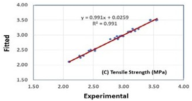
Figure 2: Relation between experimental and fitted data for density, compressive, and splitting tensile strengths of the PSC mixes
Analysis of Variance (ANOVA)
The estimated regression coefficients are shown in Table 5, for each of the output responses. Based on the obtained data, regression equations, that have the same terms, were obtained for PSCM for each response (i.e., density, compressive strength, and splitting tensile strength). As shown in the table, most of the terms are significant with a p-value less than 0.05. Some others are less significant but are included in the model to keep the same terms of density, and compressive and splitting tensile strengths. The suggested model for the density (Y1), compressive strength (Y2), and splitting tensile strength (Y3) was adequate because its p-value of lack-of-fit was greater than 0.05. This indicates that the suggested model has very good prediction levels.
|
|
Density (g/cm3) |
Compressive Strength (MPa) |
SplittingTensile Strength (MPa) |
||||||
|
Y1 |
|
|
Y2 |
|
|
Y3 |
|
|
|
|
Source |
DF |
F |
p-value |
DF |
F |
p-value |
DF |
F |
p-value |
|
Regression |
13 |
26.95 |
0.000 |
13 |
41.97 |
0.000 |
13 |
143.76 |
0.000 |
|
Linear |
3 |
4.88 |
0.013 |
3 |
8.72 |
0.001 |
3 |
54.87 |
0.000 |
|
Quadratic |
6 |
9.67 |
0.000 |
6 |
19.05 |
0.000 |
6 |
121.35 |
0.000 |
|
X1X2 |
1 |
2.42 |
0.138 |
1 |
11.43 |
0.004 |
1 |
7.21 |
0.016 |
|
X1X3 |
1 |
2.82 |
0.111 |
1 |
15.71 |
0.001 |
1 |
0.09 |
0.769 |
|
X1X4 |
1 |
11.3 |
0.004 |
1 |
12.36 |
0.003 |
1 |
186.65 |
0.000 |
|
X2X3 |
1 |
1.48 |
0.241 |
1 |
10.51 |
0.005 |
1 |
0.75 |
0.398 |
|
X2X4 |
1 |
6.63 |
0.020 |
1 |
2.26 |
0.151 |
1 |
146.1 |
0.000 |
|
X3X4 |
1 |
9.87 |
0.006 |
1 |
21.38 |
0.000 |
1 |
18.2 |
0.001 |
|
SpecialCubic |
4 |
14.22 |
0.000 |
4 |
19.91 |
0.000 |
4 |
77.71 |
0.000 |
|
X1X2X3 |
1 |
0.96 |
0.342 |
1 |
10.4 |
0.005 |
1 |
0.58 |
0.457 |
|
X1X2X4 |
1 |
3.16 |
0.093 |
1 |
0.43 |
0.520 |
1 |
85.37 |
0.000 |
|
X1X3X4 |
1 |
11.62 |
0.003 |
1 |
31.22 |
0.000 |
1 |
20.84 |
0.000 |
|
X2X3X4 |
1 |
1.09 |
0.311 |
1 |
0.45 |
0.511 |
1 |
0.08 |
0.785 |
|
ResidualError |
17 |
|
|
17 |
|
|
17 |
|
|
|
Lack-of-Fit |
3 |
1.18 |
0.354 |
3 |
2.18 |
0.136 |
3 |
0.94 |
0.448 |
|
PureError |
14 |
|
|
14 |
|
|
14 |
|
|
|
Total |
30 |
|
|
30 |
|
|
30 |
|
|
Table 5: ANOVA Regression Results
Table 5 shows that the special cubic model provides an adequate fit to the PSCM responses; density, compressive strength, and tensile splitting strength as represented by Equation 1.
Y = β1X1 + β2X2 + β3X3 + β4X4 + β12X1X2 + β13X1X3 +β23X2X3+ β14X1X4 + β24X2X4 + β34X3X4 +β123X1X2X3 + β124X1X2X4 +β134X1X3X4 + β234X2X3X4+ε (1)
\Where: Y represents the response; the variable X1 represents the binder (polymerized sulfur), X2 is the first aggregate (dune sand), X3 is the second aggregate (LFS), and X4 is the filler (GGBFS).
Density of PSCM Mixtures
The experimental results indicated that the density (Y1) of PSCM was significantly affected by all four components: polymerized sulfur, dune sand, LFS, and GGBFS. The essential quantity of polymerized sulfur is dependent on the amount of void space that should be filled, and the overall surface area that needs to be covered. On the other hand, the aggregate particle size has a significant role in the packing of the PSCM structure, where uniform-size ingredients produce high spacing between the particles and, accordingly, a higher paste requirement is required. The interaction effects were found to be significant, illustrating the benefits of performing DOE and analysis of variance when optimizing density measurements of PSCM. Mixes with higher polymerized sulfur have lower density. This is because polymerized sulfur is the lightest component of the mix and so mixes with higher binder content have lower density. It was also observed that the GGBFS has the highest impact on density. An increase in the density of the PSCM is a result of filling the mixture voids with very small filler particles (micro filler effect) [35, 36].
Based on the statistical model, all coefficients were significant, below the 90% confidence level, and the density can be expressed as shown by equation (2) with an R2 value of 0.93.
Density = 145 X1 + 54 X2 + 109 X3 + 259 X4 - 386 X1X2 - 585 X1X3 - 1185 X1X4 - 711 X2X4 -784 X3X4 + 2652 X1X2X4 3032 X1X3X4 (2)
As shown in Figure 3(a), the maximum density of the PSCM is reached at high polymerized sulfur and sand mass content (40% and 40%, respectively) as expected, however still relatively high density could be approached at the polymerized sulfur and dune sand mass content of 32 and 34%, respectively. Figure 3(b) shows that the maximum density is reached at moderate dune sand and LFS content of 34-36% and 18-20%, respectively. In addition, Figure 3(c) shows that the maximum density is reached at high LFS and GGBFS content, however, still relatively high density could be approached at LFS mass content of 20-22% and GGBFS content of 17-18%. On the other hand, Figure 3(d) shows that the maximum density is reached at a moderate GGBFS content of 17- 19% and a polymerized sulfur content of 32-36%.
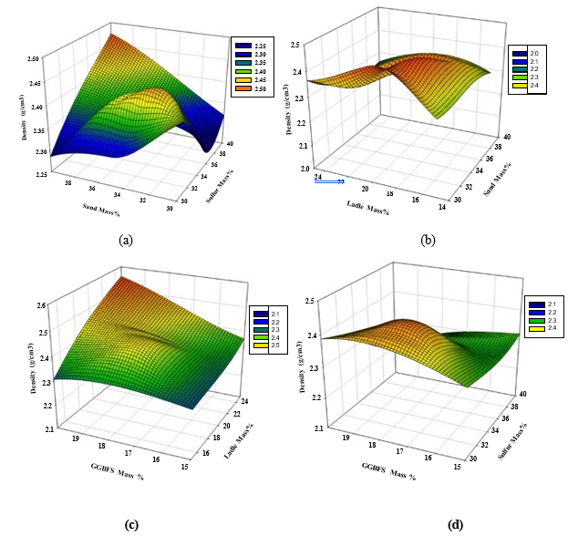
Figure 3: 3D Response surface plots for the effect of (a) sand and polymerized sulfur, (b) LFS and sand, (c) GGBFS and LFS, and (d)GGBFS and polymerized sulfur mass percentage on total density (Mg/m3)
Compressive Strength of PSCM
Notably, LFS is a crushed product having hard, dense, angular, and roughly cubical particles which can help to develop very strong interlocking properties; whilst, the polymerized sulfur can be considered as an adhesive. The connection between polymerized sulfur and the aggregates is a physical adhesion, which, depends on aggregate proportions and properties including surface texture, porosity or absorption, surface coatings, surface area, and particle size. It is generally accepted that aggregates with a porous, slightly rough surface will promote adhesion by providing for a mechanical interlocking effect [36,37].
Based on the statistical model, all coefficients were significant, below the 90% confidence level, and the compressive strength can be expressed as shown by equation (2) with an R2 value of 0.97.
Compressive Strength = 38070 X1 + 23112 X2 + 82498 X3 +16849 X4 - 131889 X1X2 - 334398X1X3 - 97869X1X4 - 235790X2X3- 8846 X2X4-182840X3X4 + 809613X1X2X3 + 587465 X1X3X4 (3)
As shown in Figure 4, the interaction effects were found to be significant. Figure 4(a) indicates that the maximum compressive strength for the PSCM can be obtained at a polymerized sulfur mass content of 32-34% and dune sand content of 30-32%. As mentioned before, the studied response was obtained at constant GGBFS and LFS of 17% and 19%, respectively.
Figure 4(b) illustrates that the maximum compressive strength can be obtained at dune sand and LFS content of 34-36% and 18-22%, respectively, with constant GGBFS and polymerized sulfur mass of 17 and 34 %, respectively. On the other hand, and as shown in Figure 4(c), the maximum response was achieved at LFS and GGBFS content of 22-24% and 18-19%, respectively, with a constant polymerized sulfur and dune sand mass of 34 and 35%. Finally, Figure 4(d) indicates that the maximum compressive strength is reached a moderate GGBFS content of 17-19% and polymerized sulfur content of 32-36%.
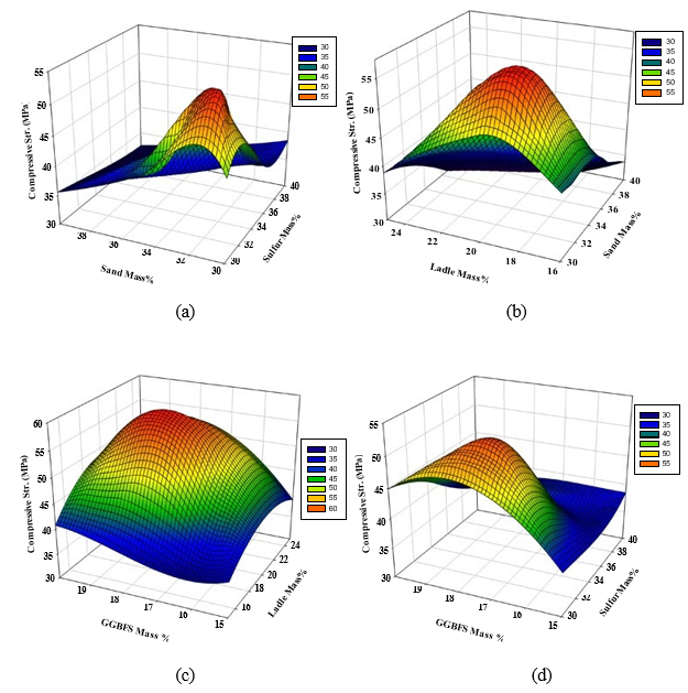
Figure 4: 3D Response surface plots for the effect of mass percentages of (a) dune sand and polymerized sulfur, (b) LFS and dune sand,(c) GGBFS and LFS, and (d) GGBFS and polymerized sulfur on the compressive strength (MPa).
Splitting Tensile Strength of PSCM
The statistical model, which was developed under varying mixture proportions to predict the tensile strength, has shown that all coefficients were significantly below the 95% confidence level and the tensile strength can be expressed by equation (4) with an R2 value of 0.99.
Splitting tensile strength = -1000 X1 – 609 X2 + 377 X3 – 4549 X4+ 3208 X1X2+14101 X1X4-2567 X2X3 + 12025 X2X4 + 5964 X3X4+ 8176 X1X2X3 – 33651 X1X2X4 – 13512 X1X3X4 (4)
The results of the splitting tensile strength test for the different mixtures are shown in Figure 5. The figure shows that the trends for splitting tensile strength are closely related, as expected. The splitting tensile strength of PSCM is around 12 to 16% of its compressive strength. Since both are dependent on the extent of particle packing in the mixture and the bond between the polymerized sulfur and other components. Therefore, a similar discussion can be assumed for the splitting tensile strength. As shown in Figure 5(a), the maximum splitting strengths can be obtained at polymerized sulfur mass content of 32-34% and dune sand content of 30-32% at constant GGBFS and LFS of 17 and 19%, respectively. Figure 5(b) shows that the maximum splitting tensile strengths can be obtained at dune sand and LFS mass content of 34-36% and 18-22%, respectively at constant GGBFS and polymerized sulfur mass of 17 and 34%, respectively. On the other hand, Figure 5(c) illustrates that the maximum splitting strengths can be obtained at LFS and GGBFS content of 22-24% and 18-19%, respectively at constant polymerized sulfur and sand of 34 and 35%. Finally, Figure 5(d) indicates that the maximum splitting strength can be obtained at maximum GGBFS and polymerized sulfur content of 19-20% and 38-40%, respectively at constant dune sand and LFS mass of 35 and 20%, respectively.
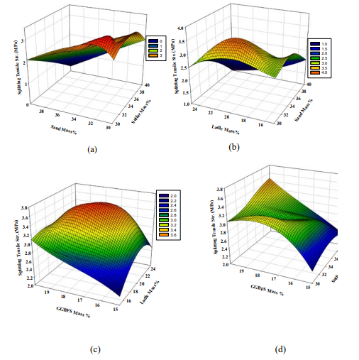
Figure 5: 3D Response surface plots for the effect of (a) dune sand and polymerized sulfur, (b) LFS and dune sand, (c) GGBFS and LFS,and (d) GGBFS and polymerized sulfur mass percentage on the splitting tensile strength (MPa).
Table 6 summarizes some optimum conditions (different ranges of mass of the mixture components) that sustain maximum responses of bulk density, compressive, and splitting tensile strengths. It is worth mentioning that at every two interacting parameters, the other parameters are assumed to be constant to visualize the 3D surface interaction between the studied parameters on the selected responses.
|
% Mass of the Mixture Component |
|||
|
Component |
Max. Density |
Max. Compressive Strength |
Max. Splitting Tensile Strength |
|
1st Compositional Group |
|||
|
Polymerized Sulfur% |
32-34 |
32-34 |
32-34 |
|
Sand% |
32-34 |
30-32 |
30-32 |
|
GGBFS% |
17 |
17 |
17 |
|
LFS% |
19 |
19 |
19 |
|
2nd Compositional Group |
|||
|
Polymerized Sulfur% |
34 |
34 |
34 |
|
Sand% |
34-36 |
34-36 |
34-36 |
|
GGBFS% |
17 |
17 |
17 |
|
LFS |
18-20 |
18-22 |
18-22 |
|
3rd Compositional Group |
|||
|
Polymerized Sulfur% |
34 |
34 |
34 |
|
Sand% |
35 |
35 |
35 |
|
GGBFS% |
17-18 |
18-19 |
18-19 |
|
LFS% |
20-22 |
22-24 |
22-24 |
|
4th Compositional Group |
|||
|
Polymerized Sulfur% |
32-36 |
32-36 |
38-40 |
|
Sand% |
35 |
35 |
35 |
|
GGBFS% |
17-19 |
17-19 |
19-20 |
|
LFS% |
19 |
19 |
19 |
Table 6: Range of Mixture Components to Produce Maximum Studied Responses
Contour Plots
To have a better view of the input parameter values that need to be adopted and the ones that should be avoided to ensure maximum responses, 2D contour plots were generated to help in visualizing such zones (red zones of high responses and dark blue zones of minimum responses). As shown in Figure 6(a), the maximum density is reached at high polymerized sulfur and dune sand contents as expected, however, still relatively high density could be approached at the polymerized sulfur and dune sand mass percentage of 32-34%. On the other hand, maximum compressive and splitting strengths can be obtained at polymerized sulfur content of 30-34% and dune sand content of 30-34% as illustrated in Figures 6(b) and 6(c), respectively.
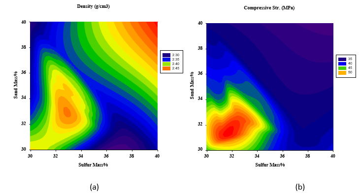
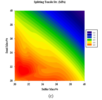
Figure 6: 2D Response surface plots for the effect of dune sand and polymerized sulfur mass % on (a) Density (Mg/m3), (b) Compressive strength (MPa), and (c) Splitting tensile strength (MPa).
Figures 7(a-c) show that the maximum density is reached at high LFS and GGBFS content as expected. On the other hand,maximum compressive and splitting strengths can be obtained at LFS and GGBFS content of 22-24% and 18-19%, respectively.
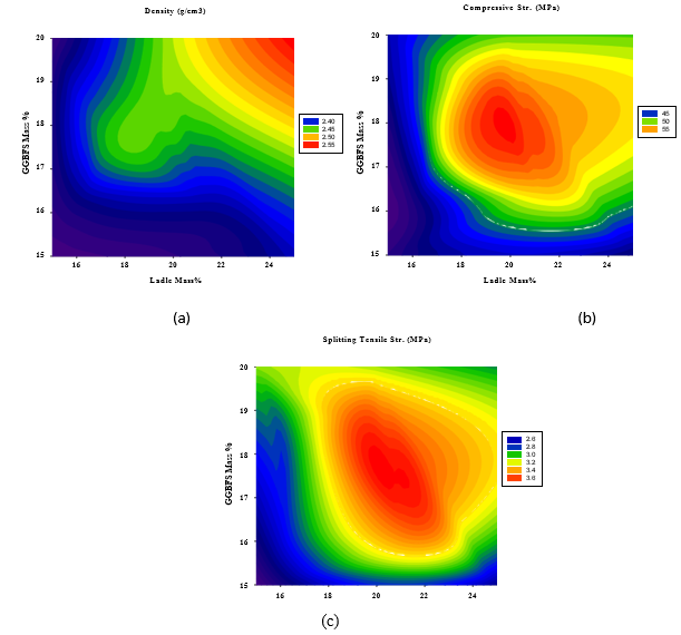
Figure 7: 2D Response surface plots for the effect of LFS and sand mass % on (a) density (Mg/m3), (b) compressive strength (MPa), and (c) Splitting tensile strength (MPa)
On the other hand, Figures 8(a-c) illustrate that the maximum density and compressive strength are reached moderate GBFS content of 17-19% and polymerized sulfur content of 32-34%, while the maximum splitting strength can be obtained at maximum GGBFS and polymerized sulfur content of 19-20% and 38-40%, respectively.
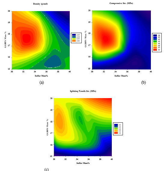
Figure 8: 2D Response surface plots for the effect of GGBFS and LFS mass % on (a) Density (Mg/m3), (b) Compressive strength (MPa), and (c) Splitting tensile strength (MPa).
Advantages of Using a Polymerized Sulfur Composite Material (PSCM) for Hydrogen Storage in Lined Rock Caverns
The shift towards hydrogen as a clean energy carrier necessitates advancements in storage technologies that ensure safety, efficiency, and environmental sustainability. Among the various options, the use of PSCM emerges as a promising alternative to Portland cement concrete (PCC) in constructing and lining man-made rock caverns for hydrogen storage. PSCM, a blend of organic polymers, waste elemental sulfur, dune sand, and alkaline solid wastes such as LFS and GGBFS, offers several distinct advantages over traditional PCC, which are:
1) Enhanced Durability and Chemical Resistance: One of the primary advantages of PSCM is its superior chemical resistance, as described in the preceding sections, particularly in environments subjected to harsh conditions [13, 30-32]. PCC, although widely used, is vulnerable to chemical attack by acids, sulfates, and other aggressive agents. This vulnerability can compromise the integrity of hydrogen storage systems over time. In contrast, PSCM exhibits remarkable resistance to such chemical agents due to the inherent properties of polymerized sulfur. Sulfur's hydrophobic nature and low reactivity protect the material from corrosive substances, ensuring a longer service life for hydrogen storage caverns. Moreover, PSCM's composition—which includes alkaline solid wastes like LFS and GGBFS—further enhances its chemical durability. These by-products contribute to the material's alkaline nature, neutralizing acidic threats and inhibiting deleterious reactions such as sulfate attack. This makes PSCM an ideal choice for lined rock caverns exposed to fluctuating environmental conditions and potential chemical contamination.
2) Superior Mechanical Properties: Hydrogen storage facilities require materials with high mechanical strength and resilience to withstand substantial loads and pressures. PSCM outperforms PCC in this regard, offering greater compressive and tensile strength, as discussed earlier. The polymerized sulfur matrix binds the composite components more effectively than the hydration products in PCC, resulting in a denser and more robust material. This increased strength reduces the risk of cracking and deformation under stress, ensuring the structural integrity of storage caverns. Additionally, the incorporation of dune sand and alkaline solid wastes contributes to the material's mechanical performance. Dune sand provides a stable granular structure, while LFS and GGBFS enhance the binding and pozzolanic reactions within the composite. Together, these components create a high-performance material capable of withstanding the demanding conditions of hydrogen storage [13].
3) Reduced Permeability: Hydrogen gas, being the smallest molecule, poses significant challenges for storage due to its propensity to escape through microscopic pores. PSCM offers a solution by exhibiting significantly lower permeability compared to PCC (Table 1). The dense and hydrophobic nature of polymerized sulfur creates a barrier that effectively prevents hydrogen diffusion. This property is crucial for maintaining the efficiency and safety of hydrogen storage systems, minimizing losses, and reducing the risk of leakage-related hazards. In contrast, PCC’s porous structure, formed during the hydration process, allows for the gradual permeation of gases, including hydrogen. Although various sealing techniques can mitigate this issue, they often add complexity and cost to the construction and maintenance of storage facilities. PSCM eliminates the need for such measures, providing a more streamlined and cost-effective solution.
4) Enhanced Sustainability: The use of PSCM aligns with the principles of sustainable development by incorporating waste materials into its composition. Elemental sulfur, a by-product of the petroleum refining process, is often stockpiled or discarded, posing environmental challenges. By utilizing this waste sulfur as a key component, PSCM not only addresses a waste management issue but also reduces the environmental footprint of hydrogen storage systems. Similarly, the inclusion of alkaline solid wastes such as LFS and GGBFS contributes to the circular economy by repurposing industrial by-products [32]. These materials, which might otherwise be landfilled, are integrated into PSCM to enhance its properties while minimizing the environmental impact of raw material extraction. In contrast, the production of PCC is energy-intensive and associated with significant carbon dioxide emissions, making PSCM a greener alternative.
5) Cost-Effectiveness: In addition to its environmental benefits, PSCM offers economic advantages over PCC. The use of waste materials such as elemental sulfur, dune sand, LFS, and GGBFS reduces the reliance on expensive raw materials, lowering production costs. Furthermore, the enhanced durability and reduced maintenance requirements of PSCM translate to long-term cost savings for hydrogen storage facilities. The lower permeability of PSCM (Table 1) also contributes to cost-effectiveness by reducing the need for supplementary sealing systems and frequent inspections. This simplifies the construction process and reduces operational expenses, making PSCM a financially viable option for large-scale hydrogen storage projects.
6) Thermal Stability and Safety: Hydrogen storage facilities often operate under varying temperature conditions, necessitating materials with excellent thermal stability. PSCM demonstrates superior performance in this regard, maintaining its structural integrity and mechanical properties across a wide temperature range [26,30,31]. The polymerized sulfur matrix resists thermal expansion and contraction, reducing the risk of cracking and material failure [13,26]. Additionally, PSCM’s low flammability and non-toxic nature [26] enhance the safety of hydrogen storage systems. Unlike some polymer-based materials, PSCM does not release harmful gases or substances when exposed to high temperatures, ensuring a safer operating environment.
7) Compatibility with Lined Rock Caverns: The geological stability of rock caverns is a critical factor in hydrogen storage. PSCM’s unique properties make it highly compatible with the lining requirements of these structures. Its dense and adhesive nature allows it to form a seamless bond with rock surfaces, preventing water infiltration and gas leakage. This compatibility ensures the long-term stability and functionality of lined rock caverns, even under high-pressure conditions. Moreover, PSCM’s adaptability allows for the customization of its properties to suit specific geological and operational requirements. By adjusting the proportions of its components, engineers can optimize the material for different storage scenarios, further enhancing its versatility and applicability.
Summary and Conclusion
This study focuses on the development of a novel polymerized sulfur composite material (PSCM) composed of a blend of organic polymer, waste sulfur, dune sand, and alkaline solid wastes, including Ladle-Furnace Slag (LFS) and Ground Granulated Blast Furnace Slag (GGBFS). The density and mechanical properties of the PSCM were evaluated experimentally. As expected, the GGBFS improved the bulk density by filling the inside structure pores, and accordingly better-packing properties of the particles have been reached. On the other hand, LFS developed very strong interlocking properties, which led to improving the physico- mechanical properties. In addition, the dune sand material allows the molten polymerized sulfur to adhere in a very easy way over its surface. The results indicated that the maximum density could be reached at high polymerized sulfur and dune sand contents, however, still relatively high density could be approached at the lower polymerized sulfur and dune sand mass percentage of 32-34%. In addition, the maximum splitting strength can be obtained at maximum GGBFS and polymerized sulfur contents and maximum compressive strength could be reached at LFS and GGBFS contents of 22-24% and 18-19%, respectively. The statistical modeling of the PSCM mixture design has indicated that it is a powerful tool for determining the significance of independent variables and their effect on the physico-mechanical properties of the produced PSCM and the ability to optimize the mixture proportions for maximizing its properties.
The advantages of using polymerized sulfur composite material (PSCM) over Portland cement concrete (PCC) for hydrogen storage in man-made lined rock caverns are compelling. From enhanced durability and mechanical strength to reduced permeability and environmental sustainability, PSCM addresses the critical challenges associated with hydrogen storage. Its cost- effectiveness, thermal stability, and compatibility with rock cavern linings further reinforce its suitability for this application.
As the demand for hydrogen storage infrastructure continues to grow, the adoption of innovative materials like PSCM will play a pivotal role in ensuring the safety, efficiency, and sustainability of these systems. By leveraging the unique properties of PSCM, the energy industry can advance towards a cleaner and more sustainable future, paving the way for the widespread adoption of hydrogen as a key energy carrier.
References
- Lindblom, U. E. (1985). A conceptual design for compressed hydrogen storage in mined caverns. International journal of hydrogen energy, 10(10), 667-675.
- Stille, H., Johansson, J., &Sturk, R. (1994, August). High pressure storage of gas in lined shallow rock caverns—Results from field tests. In SPE/ISRM Rock Mechanics in Petroleum Engineering (pp. SPE-28115). SPE.
- Sofregaz, U., &Gustafsväg, C. (1999). Commercial potential of natural gas storage in lined rock caverns (LRC). US Department of Energy.
- Lord, A. S., Kobos, P. H., &Borns, D. J. (2014). Geologic storage of hydrogen: Scaling up to meet city transportation demands. International journal of hydrogen energy, 39(28), 15570-15582.
- Lord, A. S., Kobos, P. H., &Borns, D. J. (2014). Geologic storage of hydrogen: Scaling up to meet city transportation demands. International journal of hydrogen energy, 39(28), 15570-15582.
- Zivar, D., Kumar, S., &Foroozesh, J. (2021). Underground hydrogen storage: A comprehensive review. International journal of hydrogen energy, 46(45), 23436-23462.
- Elberry, A. M., Thakur, J., Santasalo-Aarnio, A., &Larmi, M. (2021). Large-scale compressed hydrogen storage as part of renewable electricity storage systems. International journal of hydrogen energy, 46(29), 15671-15690.
- Nilsen, B., & Olsen, J. (Eds.). (2022). Storage of Gases in Rock Caverns: Proceedings of the International Conference on Storage of Gases in Rock Caverns/Trondheim/26-28 June 1989. Routledge.
- Semprich, S., Crotogino, F., & Schneider, H. J. (1990). Storage in lined hard-rock cavens: results of a pilot study. Tunnelling and underground space technology, 5(4), 309-313.
- Johansson, J. (2003). Cavern wall design principles (Doctoral dissertation, Byggvetenskap).
- Masoudi, M., Hassanpouryouzband, A., Hellevang, H., &Haszeldine, R. S. (2024). Lined rock caverns: A hydrogen storage solution. Journal of Energy Storage, 84, 110927.
- Johansson, F., Spross, J., Damasceno, D., Johansson, J., &Stille, H. (2018). Investigation of research needs regarding the storage of hydrogen gas in lined rock caverns: Prestudy for Work Package 2.3 in HYBRIT Research Program 1.
- Mohamed, A. M. O., & El Gamal, M. (2024). A Novel Polymerized Sulfur Concrete for Underground Hydrogen Storage in Lined Rock Caverns. Sustainability (2071-1050),16(19).
- Jones, R. H., & Thomas, G. J. (2007). Materials for the hydrogen economy. CRC Press.
- Gajda, D. A. W. I. D., Liu, S. H. I. M. I. N., &Lutynski, M.(2021). The concept of hydrogen-methane blends storage in underground mine excavations–gas permeability of concrete. In E3S Web of Conferences (Vol. 266, p. 03007). EDP Sciences.
- Gajda, D., &Lutynski, M. (2021). Hydrogen permeability of epoxy composites as liners in lined rock caverns— experimental study. Applied Sciences, 11(9), 3885.
- Gajda, D., &Lutynski, M. (2022). Permeability modeling and estimation of hydrogen loss through polymer sealing liners in underground hydrogen storage. Energies, 15(7), 2663.
- Masoudi, M., Hassanpouryouzband, A., Hellevang, H., &Haszeldine, R. S. (2024). Lined rock caverns: A hydrogen storage solution. Journal of Energy Storage, 84, 110927.
- Kim, H. M., Rutqvist, J., Kim, H., Park, D., Ryu, D. W., & Park, E. S. (2016). Failure monitoring and leakage detection for underground storage of compressed air energy in lined rock caverns. Rock Mechanics and Rock Engineering, 49, 573-584.
- Lee, D. H., Lee, H. S., Kim, H. Y., &Gatelier, N. (2005, May). Measurements and analysis of rock mass responses around a pilot lined rock cavern for LNG underground storage. In ISRM EUROCK (pp. ISRM-EUROCK). ISRM.
- Jiang, Z., Li, P., Tang, D., Zhao, H., & Li, Y. (2020).Experimental and numerical investigations of small-scale lined rock cavern at shallow depth for compressed air energy storage. Rock Mechanics and Rock Engineering, 53, 2671- 2683.
- Munger, C. G. (1985). Corrosion prevention by protectivecoatings.
- Golewski, G.L. (2023) The Phenomenon of Cracking in Cement Concretes and Reinforced Concrete Structures: The Mechanism of Cracks Formation, Causes of Their Initiation, Types and Places of Occurrence, and Methods of Detection—A Review. Buildings 2023, 13(3), 765.
- Mohamadian, N., Ramhormozi, M. Z., Wood, D. A., &Ashena,R. (2020). Reinforcement of oil and gas wellbore cements with a methyl methacrylate/carbon-nanotube polymer nanocomposite additive. Cement and Concrete Composites, 114, 103763.
- Mohamed, A. M. O., & El-Gamal, M. (2010). Sulfur concrete for the construction industry: a sustainable development approach. J. Ross Publishing.
- Ciak, N., &Harasymiuk, J. (2013). Sulphur concrete’s technology and its application to the building industry. Technical Sciences/University of Warmia and Mazury in Olsztyn, (16 (4), 323-331.
- Vroom, A. H. (1981). U.S. Patent No. 4,293,463. Washington,DC: U.S. Patent and Trademark Office.
- Mohamed, A. M. O., & El Gamal, M. M. (2014). U.S. Patent No. 8,859,719. Washington, DC: U.S. Patent and Trademark Office.
- Mohamed, A. M. O., & El Gamal, M. (2009). Hydro-mechanical behavior of a newly developed sulfur polymer concrete. Cement and Concrete Composites, 31(3), 186-194.
- Mohamed, A. M. O., El-Dieb, A., Sawy, K. M. E., & Gamal,M. M. E. (2015). Durability of modified sulfur concrete in sewerage environment. Environmental Geotechnics, 2(2), 95-103.
- Mohamed, A.M.O., El Gamal, M.M., and Hameedi, S. (2022). Sustainable utilization of carbon dioxide in waste management. Elsevier.ISBN 9780128234181, 606p.
- El Gamal, M., El-Sawy, K., & Mohamed, A. M. O. (2021). Integrated mixing machine for sulfur concrete production. Case Studies in Construction Materials, 14, e00495.
- Fowler, D. W. " Guide for Mixing and Placing Sulfur Concrete in Construction. Report of ACI Committee, 548.
- Dotto, J. M. R., De Abreu, A. G., Dal Molin, D. C. C., & Müller, I. L. (2004). Influence of silica fume addition on concretes physical properties and on corrosion behaviour of reinforcement bars. Cement and concrete composites, 26(1), 31-39.
- Tarrer, A. R. (1991). The effect of the physical and chemical characteristics of the aggregate on bonding.
- Crumpton, C. F., Smith, B. J., & Jayaprakash, G. P. (1989). Salt weathering of limestone aggregate and concrete without freeze-thaw. Transportation Research Record, (1250).