
Journal of Pathology and Laboratory Medicine(JPLM)


Research Article - (2023) Volume 1, Issue 1
Disabling And Disposing System For Electronic Syringe And Needle
2South Regional Health Ofice, Hawassa, Ethiopia
3Diredewa Hospital, Diredewa, Ethiopia
Copyright: ©©2023: Ahmed Ali Dawud. This is an open-access article distributed under the terms of the Creative Commons Attribution License, which permits unrestricted use, distribution, and reproduction in any medium, provided the original author and source are credited.
Citation: Dawud, A. A., Firisa, A., Abagaro, A. M., Abduresak, A. (2023). Disabling And Disposing System For Electronic Syringe And Needle. J Path Lab Med, 1(1), 25-31.
Abstract
In developing countries, most hospitals are lacking in needle safety. In regions surveyed by the world health organization (WHO), the reported number of needle stick injuries in developing world countries ranged from .93 to 4.68 injuries per person and per year, which is five times higher than in industrialized nations.
There are a lot of infections related with needle reuse problems especially in developing countries like Ethiopia, since the most common method for disposing of used hypodermic needle syringes is a sharps container and general waste incinerator in the hospital. A study by World Health Organization indicates that about 12 billion injections are adminis- tered each year. The most clinical significance that we approach our design is the common method for disposing of used hypodermic needle syringes is a "sharps" container. A sharps container merely is a plastic container into which the used hypodermic needle syringes are placed which lead to unintentional contact with a contaminated needle and exposing the contaminated needles.
Our design consideration generally consists two main parts: Electrical parts, the power development part for the proper destruction of the needle and the syringe to develop a large amount of current from a wall socket which helps to destroy a needle, consisting step down transformer, bread board, switch, Full wave rectification, fuse, resistor and flat capacitor for power filtration, while the mechanical parts consist a frame box of metal which is made up of carbon plated metal having high melting point to resist the heat like carbon metal which is one of the best heat resistant metal to melt a nee- dle. The needle destroying means comprises two overlapping flat electrodes preferably comprised of high grade carbon. The electrodes may be comprised of any suitable electrode material; however, high grade carbon provides the preferred electrical conduction level and has a satisfactory lifetime.
Finally, the designed device is that the user simply holds the injector and plugs the used needle head into the needle-head destroy device so that the needle is in contact with both non-contacting electrodes. At this moment the used needle will absorb the strong current resulting from short-circuit of the two electrodes, while the detachment, and the collection of the needles can be done all at once to s simplify the operation.
Keywords
Carbon, Current, Disabling, Heat, Needle.Introduction
Biomedical waste is waste that is either putrescible or potentially infectious. Biomedical waste may also include waste associated with the generation of biomedical waste that visually appears to be of medical or laboratory origin e.g., packaging, unused bandages, infusion kits, etc. as well research laboratory waste containing bimolecular or organisms that are restricted from environmental release. Usually hospital people either throw away used syringe needles or sterilize them and reuse them. In case that these needles are thrown away, infections may be spread out and may endanger (carelessly hurt human bodies and cause infections) cleaners’ health.
If these needles are reused, they may hurt medical people and cause infections in the process of detaching, sterilizing and storing these needles. For security considerations, basically all medical people usually throw away their needles. In view of this, this invention is made to provide an electrical syringe needle disposal system [1].
Our instant analysis relates to medical safety apparatus, and more particularly to an apparatus for destroying used hypodermic needles in order to minimize the risk of transmitting diseases to healthcare workers through needle disabling and destroying system. It has been found that annually a significant number of healthcare workers are infected with blood-borne diseases through inadvertent needle pricks from used hypodermic needles.
It has been further found that although the likelihood of contracting a serious blood-borne disease through a single needle prick may be relatively small, the consequences can be extremely serious. In this connection, because needle pricks provide direct access to the venous systems of healthcare workers, it is possible for such workers to contract serious diseases, such as AIDS or hepatitis B through inadvertent needle pricks[2].
There are a lot of infections related with needle reuse and disposal problems especially in developing countries like Ethiopia as shown in figure1; in this section we focus only in HIV/AIDS because of HIV/AIDS is the common problem of all over the world at this time. Current medical practice favors one-time use of needle syringes over reusable syringes. After a one-time use hypodermic needle syringe has been used, it must be disposed of properly[3].
The most common method for disposing of used hypodermic needle syringes is a sharps container A sharps container merely is a plastic container into which the used hypodermic needle syringes are placed. When the container is full, a cap is placed on the container and the container is disposed of[4,5].
Typically, a service picks up the full sharps' containers and disposes of the full containers either through incineration or in landfills. When destroyed in incinerators, the sharps container provides a sufficient method of disposal of the used hypodermic needle syringes. However, sharps containers suffer from several disadvantages. First, the used hypodermic needle syringes are not sterilized before being placed in the sharps' container. This can lead to unintentional contact with a contaminated needle. Second, if the sharps' containers are disposed of in a landfill, there always the possibility that the sharps' container can inadvertently open or be broken thus exposing the contaminated needles[6,7].
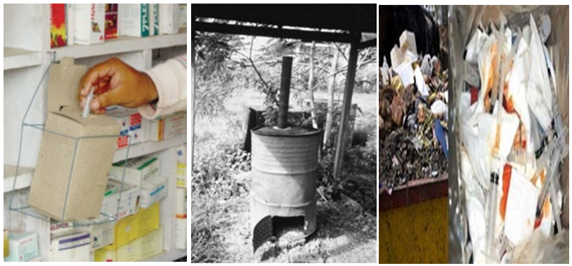
Figure1: Existing solution in Ethiopian hospitals
Source: - Ethiopian hospital waste disposal system Google image
Methods
Biomedical waste is distinct from normal trash or general waste, and differs from other types of hazardous waste, such as chemical, radioactive, universal or industrial waste. Medical facilities generate waste hazardous chemicals and radioactive materials. While such wastes are normally not infectious, they require proper disposal.
Disposal of this waste is an environmental concern, as many medical wastes are classified as infectious or bio hazardous and could potentially lead to the spread of infectious disease we try to find a solution for this issue to provide an apparatus for destroying needles which is a compact, standalone unit which can be used by hospital wards, individual hospital rooms, and doctors’ examining rooms, dental or veterinary practices [8,9].
Our team member brain storm, deeply discuss how to overcome the problem and prose the following different solutions for the design progress. The first solution is to provide an electronic syringe needle destroyer with a power control switch, a circuit protecting device (fuse), a transformer, and two inter-crossing, non-contacting electrodes which can bring about ash electric-heat to destroy syringe needles and having collecting box for residue.
While the other solution is to provide an apparatus for destroying the needle component of a syringe by destroying and/or incinerating the metal needle component of the syringe and removing any remaining portion of the needle by cuter to provide an apparatus for destroying needles which renders any unburned portions of the needle sterile and not harmful to the operator and other humans. Another solution is also introduced electrical arc across the two electrodes while the temperature sensor is provided that senses the temperature of the atmosphere adjacent the electrodes. When this temperature exceeds a pre-set level, a switch actuator is activated to open the circuit and remove power from the electrodes. But has a great challenge due to component availability locally.
Finally we agreed to design a device for destroying the needle component of a syringe by destroying and/or incinerating the metal needle component of the syringe and removing any remaining portion of the needle by cuter, Which renders any unburned portions of the needle sterile and not harmful to the operator and other humans. It is another object of the present invention to provide an apparatus for destroying needles.
Our design consideration generally consists two main parts: Electrical parts, which includes the power development part for the proper destruction of the needle and the syringe. Main designation is for rectification (AC-DC) and to develop a large amount of current from a wall socket which helps to destroy a needle, consisting step down transformer, bread board, switch, Full wave rectification, fuse, resistor and flat capacitor for power filtration.
Mechanical parts consist a frame box of metal which is made up of carbon plated metal. Since the burning mechanism creates high amount of heat; to resist this huge amount of heat the metal must be high melting point and carbon metal is one of the best heat resistant metal, its melting point is around 3400 °C and this is enough for us which needed 1400 °C to melt a needle.
Final Design
The designed device generally comprises a rectangular box with a needle alignment plate located under the cover. The interior of the box is provided with the main Working components of the present invention: the electrode assembly, the power assembly for reciprocating the electrode and the container for collecting burned needle residue. The needle alignment plate is mounted to the underside of the cover of the apparatus and is spring-biased upwardly. The alignment plate also ensures that the needle properly engages the electrode and prevents the end of the needle from being misaligned with the electrode. The electrode is a single rod element that is positioned horizontally in a carriage. The rod electrode is mounted for rotation along is horizontal axis and the carriage is also mounted for horizontal reciprocal motion. The two main parts used for the design of the device including their specification is described as follows and the final diagram of the design is shown in figure 2.
Electrical parts; this is the power development for the proper destruction of the needle and the syringe consisting consists the following.
• Step dawn transformer (220V to 12V),
• wires that home-use power supply (110 V or 220 V),
• bread board (for the power development),
• Full wave rectification (for changing AC to DC power),
• Fuse (for protection of the device 3-15 Ampere),
• capacitor for power filtration, and
• switch
Mechanical parts: consists of frame which is made up of carbon plated metal since the burning mechanism creates high amount of heat the metal must be high melting point followed by coating. But now we use the sheet metal for the proto type the outer cover because of the other options are not available i.e. carbon plated metal and stainless steel is not available and also expensive in the market. The final drawing of the selected design is shown in figure 2 and list of different components used for construction of the prototype listed in Table1.

Figure 2: overall final diagram of selected design
Table 1: Component list for the final design of the project
|
List No. |
Item Description |
Unit Definition |
Specification |
|
1 |
Very high grade steel cutter (316 L grade) |
1 |
Cutter |
|
2 |
step down transformer(220v to 4 v) and 120 watt |
1 |
step down a voltage |
|
3 |
carbon plated metal (50cm by35cm) |
1 |
outer cover |
|
4 |
high grade carbon electrode |
2 |
melting purpose |
|
5 |
Thermistor (sense around 1400 Celsius type B |
1 |
Temperature Sense |
|
6 |
Flat capacitors(300-500 micro faraday) |
5 |
Rectification |
|
7 |
Resistor(500-1000 ohm) |
6 |
Rectification |
|
8 |
Lid switch |
1 |
Switch |
|
9 |
fuse(3-15 amp) |
1 |
protect a circuit |
|
10 |
charcoal filter (bio hazard gas filtrate) |
1 |
Filter a biogas hazard |
|
11 |
bread board(small size) |
2 |
Power development |
|
12 |
Diode (IN4001 and IN4007) |
4 |
Bridge formation purpose |
Result
The device consists of the power wires that home-use power supply (110 V or 220 V), a switch, a transformer, two electrodes and fuse. The transformer is step dawn (220V to 16V).The electrodes are high-melting carbon -coated. There is a keyhole-shaped needle-head detaching device on top of the outer case. The needle-head detaching device includes a needle-head inserting hole and a needle-head slide track with inclined sides .The needle-head inserting hole is a round hole on top of the two electrodes so that when needle-heads are inserted they will cause a downward pressure on the electrodes. A hoof-shaped supporting frame is located under the said hole, somewhat lower than the needle-head slide track, and with the same width as that of the needle-head slide track. The hoof-shaped supporting frame has a width as large as that of the needle-head slide track, but a little smaller than the needle-head shoulder, and larger than the rest of needle-head. The drawer like needle-head collector must be equipped with a heat-insulating metal plate to prevent heat dissipation in the environment [10,11].
The device provides an effective apparatus for electrically destroying used needles by instantaneously electrically heating them to temperatures in excess of the melting points of the metals from which they are constructed and for thereby converting used needles into relatively harmless powdered debris.. The housing preferably has a needle entry opening, and the guide means is preferably operative for guiding a needle inserted into the housing through the needle entry opening. In addition, the apparatus preferably includes spark shield means in the needle entry opening for shielding an operator of the apparatus against sparks generated as a needle is electrically destroyed in the housing. The spark shield means preferably includes a pair of resiliently yieldable spark shield elements, each of which has a pair of intersecting slits formed therein which is disposed in substantially perpendicular relation to each other.
The apparatus further includes filter means in the housing and fan means for drawing air inwardly into the housing through the needle entry opening so that the air passes around the electrode wheel and the electrode element and is then drawn through the filter means and exhausted from the housing. In addition, the apparatus preferably includes a cartridge in the housing which is operative for receiving debris generated when a needle is destroyed through contact with the electrode wheel and the electrode element.
The cartridge includes a container portion and a cover portion, and the container portion is preferably located in the housing so that it is operative for receiving debris generated as a needle is destroyed through contact with the electrode wheel and the electrode element. The container portion of the cartridge preferably includes primary and secondary compartments, and the primary compartment is preferably operative for receiving debris, whereas the secondary compartment is preferably operative for receiving the cover portion of the cartridge in an inoperative position wherein the cover portion is removed from the upper end of the container portion. The developed prototype is shown in figure 3.
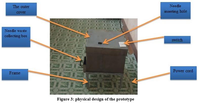
Figure 3: physical design of the prototype
Device Operations
The operations proceed as follows:
1. First press switches on for power supply.
2. After heated, insert the needle-head into the needle-head insertion hole Then the needle head forms a short circuit between the two electrodes. As the cross section of the needle-head is very small, and its electric resistance is larger than the electrodes electric resistance reversely propionates with the cross section, the needle head can completely absorb the strong current resulting from the ash of short circuit. The needle-head will thus be melted and deformed by the high temperature enabling the injector to move downward until the needle-head flange is stuck by supporting frame.
3. Then the injector and the needle-head can be moved along to the other side of the needle-head slide track. Since the supporting frame is a little lower than the needle-head slide track, the flange of the needle-head, will be stuck under the needle-head slide track.
4. Hence in the sliding process the needle-head that could be destroyed at any time is separated from the injector by the inclined guide track walls and drops on a metal plate in the needle head collecting box and completes destroying, detaching, and needle-head collecting safely. Since transformer decreases several times the input voltage such that the voltage across the electrodes is only 12-16 voltages, limiting the fuse current between a safe range of 5-30 Amp. The fuse current is 5-30 Amps. When accidental short-circuit on the electrodes is incurred by any accidental objects, the fuse will be burned up to cut off power and prevent any extension of danger [12].
The heat generated by the electrical circuit is sufficient to sterilize any ash or melted needle portion from needle. Therefore, the needle debris contained in debris box is non-biohazard and can be disposed of in any conventional manner. Likewise, the nub and any other portion of needle remaining on syringe have been heated to a temperature high enough to sterilize. Therefore, the DE needled hypodermic needle syringe is then removed from the burner unit and can be destroyed using any conventional barrel destruction unit or, preferably, the barrel sterilization and compactor unit disclosed and claimed in the parent application hereto. Electrodes may wear due to repeated usage. The electrodes can be replaced by removing them from shafts and substituting new electrodes. The relevant portions of the unit are releasable secured to each other to allow such an exchange of electrodes, and other parts, if necessary. When the needle debris box is full of needle refuse, for the most part ash, it can be removed from the housing. The needle refuse then can be disposed of in a correct manner.
Discussion
Functional Testing
observing the structure that fit during the frame analysis that all components fit the design specification regardless of size and component wise compatibility. The housing frame preferably has a needle entry opening, and the guide means is preferably operative for guiding a needle inserted into the housing through the needle entry opening. In addition, the apparatus preferably includes spark shield means in the needle entry opening for shielding an operator of the apparatus against sparks generated as a needle is electrically destroyed in the housing and the function of the power development can be test. The detail functional test done was shown in table2.
Table 2: functional testing
|
Items to be test |
Test description |
Testing material |
|
Very high grade steel cutter |
The cuter must full fill the criteria of 316 L grade. |
|
|
Step down transformer (120 watt) |
It must have a voltage output and exact turn ratio |
Multi meter |
|
Carbon plated metal |
Highly heat resistive |
Temperature sensor |
|
High grade carbon electrode |
Highly heat resistive |
Temperature sensor |
|
Filer Capacitor |
it gives fairly stable DC output |
Multi meter |
|
Fuse |
Continuity |
Multi meter |
|
full Wave Bridge |
Have dc voltage out put |
Multi meter |
|
bread board |
Have continuity |
Multi meter |
|
Diode (IN4001 0r IN4007) |
Have continuity |
Multi meter |
Performance Testing
includes the functional measurements of the following. The fuse current is 5-30 Amps. When accidental short-circuit on the electrodes is incurred by any accidental objects. Detailed performance test done were shown in table 3.
Output of the transform (16V) Current pass though the electrode (25-30 Ampere) The time for burning of needle (3-5second)
Table 3: performance testing
|
Items to be test |
Test description |
Testing material |
|
Step down transformer |
The measurement must greater than 85 percent of the expected voltage |
Multi meter |
|
Carbon plated metal |
have the expected heat resistive around |
Temperature sensor |
|
High grade carbon electrode |
The measurement must greater than 85 percent of the expected current that pass through it |
Multi meter |
|
Filer Capacitor |
It gives fairly and reliably stable DC output |
Multi meter |
We use temperature sensor for the measuring of temperature in the housing analysis if it is available otherwise by thermostats, Multi meter for the electrical measurements and analog clock for the time till we get the required result that we prose .the durability is may be limited by the result that we get during the testing time The test performed by the team members and the advisors, who helps us for our correctness and safety precaution to have best testing procedure.
Conclusion
The technologies for the treatment of health care waste are not well understood or widely available in developing countries. As a result, deposing made on the basis of technology may not be well informed, resulting in poor or uneconomic performance. Improper disposal of a dangerous waste can cause the adverse environmental and socio-economic effects one of the most improper disposable waste is syringe, which cannot really treat as other wastes.
In Ethiopia one of developing countries in Africa there is no application of electronic needle burner and syringe disposal, instead there is an application of traditionally made incinerator which is unsafe and cause of environmental pollutants and transmission of blood borne diseases. Therefore designing electronic needle disabling and syringe disposal creates a safe environment for doctors, nurses, pathologies, healthcare professionals and patents by avoiding of reuse of needles and syringes. the device provides an effective apparatus for electrically destroying used needles by instantaneously electrically heating them to temperatures in excess of the melting points of the metals from which they are constructed and for thereby converting used needles into relatively harmless powdered debri The device that we design is generally a rectangular box with a needle alignment plate located under the cover thereof. The inner of the box is provided with the main Working components of the present invention: the electrode assembly, the power assembly for reciprocating the electrode and the container box for collecting burned needle residue a needle head inserted in the opening there between whereby a short circuit is created between the electrodes for melting the needle portion, and the casing further including separator means for disconnecting the needle head with melted needle portion from the syringe, and collector means into which the separated needle head falls, wherein the separator means comprises an elongate guide track in the top wall of the casing extending from the needle head insertion opening, the guide track having downwardly inclined side walls for receiving the needle head flange there under after melting of the needle portion whereby sliding of the needle head along the guide track effects separation of the needle head from the syringe.
Competing interests
The authors have no any competing interest
Acknowledgements
We would like to acknowledge the school of Biomedical Engineering, Jimma institute of Technology, Jimma University and Jimma University medical center for providing the requiredresources to undertake this study.
References
- OTA-O-459, finding the Rx for managing medical waste, washington DC: US government office, 2016.
- S, K. A. (2016). AIDS in the first 20 years, ethipiia: HIV and its transmission control ana prevension.
- j. upon, HIV and Its Transmission, washington: "HIV and Its Transmission". Centers for Disease Control and Prevention, 2016 .
- R, R. P. (2012). "the public health implication of medical wasate a report to congress," US Department of Health and Human Services, Public Health Service, Agency for Toxic Substances and Disease Registry, Ahtlanta.
- Kaplan, E. H., Khoshnood, K., & Heimer, R. (1994). A decline in HIV-infected needles returned to New Haven's needle exchange program: client shift or needle exchange?. American Journal of Public Health, 84(12), 1991-1994.
- Kaplan, E. H., & Heimer, R. (1995). HIV incidence among New Haven needle exchange participants: updated estimates from syringe tracking and testing data. Journal of acquired immune deficiency syndromes and human retrovirology: official publication of the International Retrovirology Association, 10(2), 175-176.
- Headquarters, W. H. O. Proposed Agenda to Evaluate the Risks and Benefits Associated with Using Needle-Removing Devices.
- R, D. Yelvington.(2007). Device for removing a needle from a Syringe, Washingtoon: Patent #5588966.
- Reinhardt, P. A. (2018). Infectious and medical waste management. CRC Press.
- C. I. L. H. D,(2016). Recirculating high velocity hot air sterilizing device, US: Yelvington Archer Aire Industries, Inc.
- Clip&Stor, Pen Needle and Syringe Needle Cutter., US:Advanced Care Products, Ltd., 2015.
- h. Raj,(2016).Needle disintegration device method and apparatus, Bombi: indian association.