
International Journal of Media and Networks(IJMN)
ISSN: 2995-3286 | DOI: 10.33140/IJMN
Impact Factor: 1.02


Research Article - (2024) Volume 2, Issue 5
Conceptual Design of a Cryocooler and Investigation of the Effect Of Design Parameters on Cryocooler Performance
2Department of Mechanical Engineering, Nooshirvani University of Technology, Babol, Iran
3Department of Mechanical Engineering, K, N. Toosi University of Technology, Tehran, Iran
4Department of Mechanical Engineering, Islamic Azad University, Saveh, Iran
Received Date: Apr 08, 2024 / Accepted Date: Apr 25, 2024 / Published Date: May 20, 2024
Copyright: ©Â©2024 Morteza Hamzeh, et al. This is an open-access article distributed under the terms of the Creative Commons Attribution License, which permits unrestricted use, distribution, and reproduction in any medium, provided the original author and source are credited.
Citation: Hamzeh, M., Kachabi, A., Andayesh, M., Fadaei, M. H. K. (2024). Conceptual Design of a Cryocooler and Investigation of the Effect Of Design Parameters on Cryocooler Performance. Int J Med Net, 2(5), 01-11.
Abstract
Pulse tube cryocooler has low vibration and high reliability because of the lack of displacer in the cold area. This advantages cause development of this cryocoolers. In some applications such as MRI systems which need cryocoolers for cooling magnet, using them will improve the imaging quality.
In this article, the steps of designing a pulse tube cryocooler which is able to be installed in MRI systems will be introduced. As conceptual design is a vital section of any design project, this part has been totally studied; Necessary data has been gathered and developed in order to have best function in the pulse tube system. Preliminary design with help of two analyses (Phasor and Isotherm analysis) is introduced to designers and important parameters are obtained. Then investigation the effect of some design parameters like valve timing, reservoir volume and pressure ratio by using isothermal analysis has been done on cryocooler performance.
Keywords
Pulse tube, Cryocooler, Designing, RegeneratorIntroduction
Cooling has always been a helping tool to improve the quality of life. As time goes on and the development of research on lower temperatures, cryogenic science has been developed. Today, cryogenics have diverse applications in the fields of medicine, space research, physics, etc. Cryogenic engineering includes the design and development of systems and components that are responsible for the production, maintenance and the use of low temperatures. One of the major cryogenic challenges was the cooling down to the helium condensation temperature. A tool for accessing cryogenic temperatures is the use of cryocooler, which is further discussed.
With variations in the orifice type pulse tube cryocooler, a system design with two inputs was made [1]. With this design they were able to reach a temperature of 42 K in one-stage mode. The intrinsic fault of multi-staging and variations such as orifice and double inlet is that their efficiency is less than stirling coolers and has more design complexity. In the mid-1990s, orifice valve in orifice type cryocoolers was replaced with a long inertance tube. In its simplest form, the inertance tube is a narrow, long pipe that produces hydraulic resistance and phase difference between the pressure of the pulse tube and its reservoir. Researcher by using an electrical analogy explained the reason for improving the performance of this system by inertance tubes [2]. They showed that in this case, the coefficient of performance of the system will increase compared to the orifice mode.
The biggest advantage of pulse tubes is the absence of a moving member in the cold area. Undoubtedly, this advantage has increased the interest of these coolers. The fact that the high dead volume is inherent in the design of these kinds of systems has led to their poor performance over stirling coolers. But in practice, pulse tubes can be comparable to Gifford coolers and in some cases even better.
An important and challenging issue in the MRI is its superconductive cooling. MRI devices require superconducting coils in order to produce a strong and uniform field and therefore high-resolution imaging. Superconductors are substances that suddenly lose their electrical resistance if their temperature is lower than the critical temperature. At present, the best superconductor of the MRI device is niobium titanium with a transition temperature of about 9 Kelvin and cooled by helium. Zhou and colleagues added a secondary input valve to the cryocooler pulse tubes of the Orifice, and introduced a structure called double inlet pulse-tube cooling. This secondary valve connected the hot tube end to the pressure source. The main reason for the success of these coolers was to improve the phase difference between mass flow and oscillatory pressure. Numerical analyses and laboratory results confirm the performance of these coolers with respect to the types of orifice. A numerical model was introduced to simulate the oscillatory flow of orifice and double inlet cryocooler [3]. This model gives a good understanding of the physics of processes occurring in the cooler. Harold developed an analytical model for the double inlet cryocooler with the use of a stepper compressor [4]. Others realized that the use of the double inlet mode would allow the direct flow of gas into the resrvoir and pulse tube [5].
Boer examined the performance of the double inlet cooler as a linear model considering the regenerator dead volume [6]. Zhang et al.analyzed the effect of reservoir volume on the thermodynamic performance of different components of the double inlet pulse tube cryocooler [7]. They made a statement to produce the entropy of each component. Others developed a phasor diagram for pulse tube coolers and gained mass flow rate in different parts of the cooler [8]. This phasor view has become an important method in analyzing the phase difference between mass flow and pressure distribution.
Definition of Problem and Conceptual Design
Understanding design limitations is important because it limits the scope of design space by eliminating unacceptable propositions. In this paper, a conceptual design for a cryocooler able to being install in a MRI system will be introduced. In the following, the conceptual design base on the limitations will be introduced.
Selection the Type of Pulse Tube
In the U-shaped tubes, the cold region of the device is easily accessible, and the heat is transmitted to the point of the target by using thermal link devices. As a result, a U-type cooler is an ideal option for installing in the MRI device. In Fig. 1, an example of a U-shaped cooler is provided.

Figure 1: U-Shaped Pulse Tube Cryocooler
Optimum Arrangement of the System In U Shape
The efficiency of the U-shaped cooler is less than the linear one, so the connection of the components must be made in such a way that the least energy loss occurs. In linear type, regenerator, cold heat exchanger and pulse tube cryocoolers, they are directly connected. But in U-shaped coolers, the three members of the interconnection pipe, the flow smoothing and the transition parts to the cold-end system will be added. The existence of interfaces at the cooler end of the cooler creates an empty space in the cooler and the backflow, which will be a factor in the turbulence of the pulse tube. In real cryocoolers, the connection pipe should not be connected directly to a cold heat exchanger or pulse tube. The reason for this is that a sudden change in the cross section of the flow causes turbulence flow. The use of cone geometry at the junction will not cause such problems. The diameter of one end of this new cone shaped member is equal to the diameter of the interconnection tube and the diameter of the other end of the regenerator diameter or pulse tube. The interface pipe, the transfer parts, and the cold heat exchanger are usually machined on the copper block. Therefore, considering the same temperature for these three members seems logical.

Figure 2: U Shape Cooler Structures
In Fig. 2, three structures are applicable to the U-shaped cryocooler of the project. In mode (a), the pipe between the cold heat exchanger and the pulsed tube is installed. As stated in the project objectives, cooling capacity is considered at 4.2 Kelvin. As a result, the cryocooler is worthy of the highest efficiency. According to the experiments carried out in (a) and (b), efficiency in (a) is greater than (B). As a result, the pipe between the cold heat exchanger and the pulse tube is connected.
Although the use of cone-shaped sections (transmission sections) is necessary to reduce the crosssectional effect, another member has to be added to the set so that the flow in the pulse tube is smooth. As a result, a series of plates (flow smoothing) should be placed between the cone member and the pulsed tube to remove the current from turbulence and calm down. Of course, it needs to be explained that if you use more grid pages, this member will act like a regenerator and will have an adverse effect on the system efficiency. As a result, although networking has a positive effect on the relaxation of current, the material of this member should be selected sexually, having less thermal conductivity, density, and heat capacity. With this choice, the smoothing effect on the efficiency can be ignored.
Pulse Tube Valve Mechanism
There are two kinds of pulse tube cooler according to the valve mechanism. In Table 1, these two types and features are given:
|
Type of Pulse Tube Cooler |
GM Type |
Stirling Type |
|
Frequency of operation |
1-5 Hz |
20-120 Hz |
|
Compressor connection |
with valve |
Directly |
|
compressor |
Lubricated |
Dried |
|
performance factor |
Low |
High |
|
pressure ratio |
High |
Low |
|
minimum temperature |
less than 2 Kelvin in two-stage mode |
about 20 Kelvin in two-stage mode |
|
compressor capacity |
several kilowatts (bulk compressor) |
several hundred watts (small compressor) |
Table 1: Specifications of Pulse Tubes Based on the Valve Mechanism
In the GM type tube, the frequency of the cooler is synchronous with the valve frequency. This is when the frequency of the stirling coolers is equal to the compressor frequency. Due to the high frequency and the lack of valve in stirling type, the cooling power of these coolers is higher than GM ones. But the high frequency of stirling coolers limits the performance of these coolers at low temperatures, especially at temperatures below 10 K. In fact, in this temperature range, it is necessary to give the system enough time to create cooling. Because at these temperatures, the heat dissipation of the system in each cycle is very low. The GM type cooler schematic is shown in Fig. 3.

Figure 3: GM Type Pulse Cryocooler Schematic
Generally, rotary valves are used to create the oscillatory pressure required in these systems. The mechanism of the valve separates the compressor and pulse tubes. This eliminates the vibration of the compressor into the cooler assembly. It is also possible to achieve temperature of 4 K.
Pulse Tube Type Based on Phase Shift Mechanism
The phase shift mechanism has a significant effect on overall cryocooler performance. Four main mechanism of phase change are simple, orifice, inertance, and double inlet. The choice is based on the ability to generate a cool temperature of 4.2 K. In order to achieve lower temperatures, the structure of the double inlet using the extra orifice will be used. This point is understandable in the phasor analysis section. In these coolers, the hot end of the pulse tube is connected to the regenerator hot end through an orifice valve. This additional valve reduces flow through the reservoir. At a glance, it may seem like adding a valve and considering its drop, the cooler's performance is compromised. But with the fact that the secondary inlet slows down the energy loss, the overall performance of the system also improves.
• Regenerator
Regenerator is a critical component of the processor working with oscillating flows. Ideally, Regenerator has the following properties:
- Materials with high thermal capacity
- Full heat transfer between the passing gas and the enclosure
- Resistance to zero current in matrix enclosure
- Porosity near zero
- Thermal conductivity in flow direction equal to zero
- Ideal gas flow
With these interpretations, the choice of the material used in the recovery is an important parameter for the cryocooler designer. The diameter of the used ballasts also affects the performance of the cooler. The regenerator size and pulse tube are usually optimized based on the gas flow rate from the compressor. In regenerator, we need to use high-capacity materials as a material for it. Because the redundant energy between the fluid and the matrix enclosure depends directly on the thermal capacity of the component material. It's also worth noting that Cp reduces most materials by decreasing the temperature. At temperatures below 10 K, the thermal capacity of the material usually reaches zero. Lead is one of the materials that meet the needs of up to 10 Kelvin. If, at temperatures below 10 K, there is a need for a material that has a heat transfer capacity with helium gas, because helium gas has a very low heat at low temperatures. Recently, a combination of Rare Earth Materials (Materials that have very high heat capacity at very low temperatures) was discovered that could be used as a regenerator material. The discovery of these materials kept alive the hopes of achieving helium temperature. The physical mechanism that increases the specific heat of matter is the change of the magnetic phase from the irregular phase to the regular phase. Er1-xDyxNi2, ErNi and Er3Ni are examples of these materials.
In a two-stage 4 K cryocooler, the first step is lead, and in the second step, Er3Ni, or as a combination of rare earth material. Fig. 4 shows the thermal capacity of the materials usable at temperatures below 30 K.

Figure 4: Heating Capacity of Suitable Regenerator Materials at Temperatures Below 30 k [11].
• Preliminary Design
In order to optimize design and estimate the performance of the system, it is necessary to model the cryocooler. On the other hand, the complexity of the periodic flow makes the analysis more difficult in pulse tubes. Experimental methods are difficult to design or optimize the pulse tubes parameters. A method of understanding processes is the numerical investigation of the governing equations of a problem. It is necessary to note that most initial calculations in design processes are based on simple thermodynamic or one-dimensional flow models. Three important analyses of these systems with different precision are:
- First-order analysis, phasor analysis
- Second-order analysis, such as isotherm analysis, the effect of thermodynamic asymmetry, etc.
- Third-order analysis of numerical methods, CFD and...
In the preliminary design section, the first stage of the cryocooler will be analysed and the values of the design parameters will be checked. According to Fig. 5, a pulse tube cryocooler must be achieved at a temperature of about 27 K in no load state to produce at least 40 watts of cooling in 40 K. As a result, we will base the design on no load temperature and study the design results to achieve this temperature.

Figure 5: Cooling Charge Diagram in two 4-Kelvin Cryocooler Stages (Xu et al, 2006)
Phase change mechanism is an important mechanism for cooling more in pulse tube cryocoolers. The importance of using these mechanisms is determined by using phasor analysis. As mentioned in the double inlet cryocooler, the gas after compression in the compressor will be under the operation of two orifices. These two orifices change the phase difference. Phasor analysis has been applied to this study to better known sensitive parameters.
• Phasor Analysis
The assumptions of this analysis include:
1. The thermodynamic processes inside the pulse tube are assumed to be adiabatic. That is, no thermal heat enters or goes out of the pipeline
2. The pressure in the whole system is assumed to be constant,that is, there is no compressive loss along it.
3. The pressure P and the temperature T change sinusoidal. The distribution of the pressure and temperature sinusoid is assumed to be:
P= P0 + P1cos (wt) (1)
In these relationships, P0 and T0 are respectively the average pressure and temperature. Also, P1 and T1 are the domain of the desired quantity changes. The mass flow rates within the system are named as:
mc: Mass flow rate within CHX
mpt: Mass flow rate at pulse tube center
mh: Mass flow rate inside HHX
m0: Mass flow rate in orifice
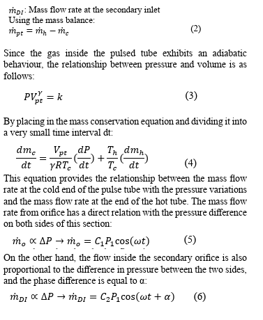

Figure 6: Two-Input Cooler Schematic
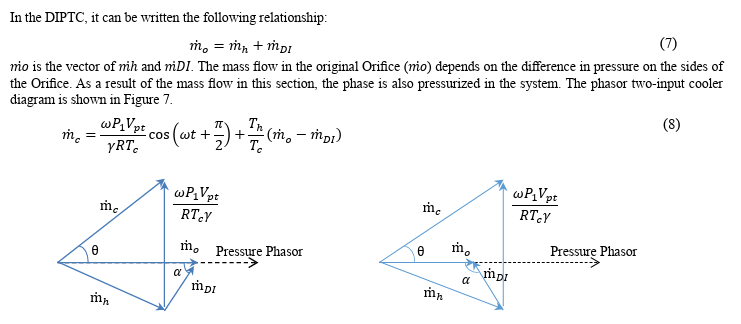
Figure 7: Phasor Input Cooling Diagram
It can be seen that the angle θ has been decreased in Figure 7, which is a feature of the double inlet cooler. The phase diagram for other parts of the cryocooler can also be drawn. For example, the process for obtaining a phase diagram for regenerator is described and will be obtained in other subsystems in the same way. As stated in the assumptions, the thermodynamic process in pulse tube is assumed adiabatic. The thermodynamic process in other parts is assumed as isotherm. By writing the relationships in the same way as before, regenerator mass flow will be obtained as follows:

Design with Phasor Analysis
The control volume around the cold heat exchanger is considered as Fig. 8 The parameters
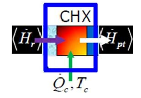
Figure 8: Control Volume Around Cold Heat Exchanger
According to the first law of thermodynamics in the respective volume of control

In the case of a full recovery function, the pure thermal energy stored in it is zero in a cycle. This means that the energy that gas at the condensing stage in this part loses is equal to the amount of energy that gas at the expansion stage, < Hr >= 0.
To check the cooling rate, the values of these four parameters should be considered. In the problem of the project, the value of Tc is constant, and it is necessary to check the cooling values by controlling the other three parameters. To get more cooling, more compression of the gas in the compressor is required. As a result, the larger the compressor will be, the more cooling in the cold zone. By choosing a larger compressor, the overall dimensions of the system will also increase. Also, the ratio cryocooler diagram has shown that its angle θ is related to the operating frequency, pressure range, pulse tube volume, and angle α. Therefore, designing these parameters in the design of the cryocooler will play a major role in cooling.
By observing the phasor diagram, we find that the amount of cooling power in the two inputs depends on the angle α. With respect to relation (18), in order to achieve a higher cooling rate can be increased to some extent. As the relation (18), than an orphan state, in the same way as the orifice opening, the 1 0 the smaller the θ, the better the cryocooler will perform. As a result, in a given design, the maximum cooling temperature occurs at the minimum of the phase angle. The phasor two-input angle of this angle should be greater than 90 degrees.
By increasing the angular value of α, the vector m.c will be further increased on the axis of pressure. This value, in the case of a secondary orphan valve, is related to the cooling power of it as a simple orphan mode. In general, with an increase in the value of α, the angle θ will decrease. This will increase cooling power.
Isotherm Analysis
Isotherm analysis is a useful analysis for sterilization chalks because of its relative simplicity. This analysis is also introduced for pulsed tube cryocoolers, and second-order analysis. This model is an important analysis in the design of the cryocooler due to its simplicity and the choice of near real assumptions. The isotherm model used in this project is based on the previous model (Zhou and Chen, 1994). They obtained the equations for the Orifice pulse tube of a Stirling cryocooler. In this article, these equations are rewritten for two inputs for a pulse tube cryocooler. In addition, due to the valve mechanism and its GM, the equations for this type of valve are also rewritten and its code is written in MATLAB software.
The analysis process is that the gas inside the pulsed tube is divided into three parts, and the gas in its middle part, an adiabatic process, and in the other two parts, experiences isothermal process. The proposed model is more complex than the proposed model for sterilization chillers.
Model Assumptions
In Fig. 9, the schematic of the cryocooler is represented by two inputs of the pulse tube.

Figure 9: Double-Input Cooler Schematic With Valve
The Assumptions Used in the Isotherm Model are as follows:
-The pressure in the entire system changes only with time.
-The process of gas in zone II, adiabatic and in other areas is considered as isotherm.
-Orifice works perfectly.
-Resistance to flow is zero.
-Gas shows ideal behavior at all points.
According to Fig. 9, the pulsed tube is divided into three parts. Two parts I and III are respectively a hot and cold area of the pulsed tube and are in thermal equilibrium with their adjacent heat exchangers. The mid-section of the pulsed tube does not flow out of the pulsed tube following the pressure variation and flows through the entire process inside the pulsed tube. So it can be assumed that it is similar to the one being moved in sterilization chillers. The motion of the gas piston is controlled by the flow of gas inside the orifice. Therefore, the concept of sterling isotherm model can be used for cooling the pulse tube.
In the end, to display the results, the parameters of the repeater solver are put into the following relationships to obtain results such as input power, cooling power, mass flow rate, and pressure ratio.
Design Using Isotherm Analysis
Timing of Valve in Control Valve
Due to the fact that there are two low-pressure and high-pressure gantry lines in the GM type coolers and, according to the valve's mechanism, these two lines are connected to the recovery valve, the timing of the valve opening and closing will affect the cooler's performance. This effect is visible through recent isotherm analysis. The pressure distribution is assumed with respect to the relationship as a trapezoid (Fig. 10).

Figure 10: Distribution of Trapezoidal Pressure
In order to evaluate the performance, several different scheduling procedures have been applied in the control valve and its effect on the cooling function of the cryocooler has been investigated.
To reduce the time and cooling parameters, values of t0 and Q0 have been used, which correspond to 1/4 cycles and equivalent cooling power, respectively.

Figure 11: The Effect of Valve Timing
As shown in Fig. 11, the flow change from the high pressure line to the low pressure line of the compressor should be around 1/40 cycles per cycle. As a result, vavle timing can be interpreted accordingly.
Reservoir Tank Volume
The reservoir at the end of the pulsed tube is connected to the system by Orifice. The size of the tank will affect the system's performance. In order to investigate this effect, the cooler cooling power changes have been investigated. In Fig. 12, the dimensionless diagram of the reservoir volume and cooling capacity is presented. V0 is equal to the volume of one liter reservoir and Q0 is the cooling power equal to V0 volume.

Figure 12: The Effect of the Reservoir Tank Volume
As can be deduced from the diagram, increasing the reservoir volume will have a positive effect on the cooler cooling power. This effect can be neglected from some extent. In this project, the volume of the tank of 2 to 3 liters is recommended for design. Larger quantities of this volume, in addition to having no significant impact on cooling power, affect the overall system volume, which is in contradiction with the goals introduced at the beginning of the project.
Pressure Ratio
Depending on the studies performed on the cryocooler made to achieve a temperature of 4.2 K, the average pressure in most of these systems is defined to be between 1-1.5 MPa. According to this average amount of pressure, the coefficient of performance of the first stage cooler is obtained at a different pressure ratio. Fig. 13 shows this diagram. It is observed that, as the pressure ratio increases, the coolant performance increases as well. Most of the cryocoolers used to reach a temperature of 4 K at a pressure ratio of between 2.5 to 3.5.

Figure 13: The Effect of Pressure Ratio on Cryocooler Performance
Conclusion
In the conceptual design section, with the help of existing documentation and analysis on them, the general profile of the project is expressed in the following paragraphs as results of the design. Due to the working temperature required in cold head of cryocooler and the low vibration in cold head of cryocooler, the life and reliability of the cooler and the cheapness of the cooler have led to the selection of the pulse tube cryocooler in the project. According to the target temperature of 4.2 Kelvin, helium is selected as a work fluid. It also has its thermo physical properties in equation 2.1 to 2.4. Due to the possibility of access to the cold zone for use on the MRI device, the U-shaped type will have an appropriate structure. The U-shaped cooler requires additional components to improve its performance due to the loss of efficiency inherent in it.
The GM type due to its low frequency, this type of cooler provides the ability to reach a temperature of less than 10 Kelvin in two- stage mode. The addition of a secondary intake valve between the heat exchanger and the control valve output will improve the phase difference between the pressure and mass flow in the cold zone. This can also be deduced from the use of phasor analysis.
The amount of cooling power of the cryocooler in each stage was obtained by calculating the amount of heat penetrated into the system. Considering these cooling power values, the design process continues. Due to the fact that some of the cryocooler are installed in a strong magnetic field, the effect of the field on the performance of the cryocooler and the proposed solution were raised. The regenerator as a key member of this collection was discussed in detail. The choice of the materials used in the regenerator was also explained by the characteristics of those materials at the desired working temperature.
In the preliminary design section, two different analyses were proposed for the designer's tools. Because the designer is not able to choose these values with basic calculations and simple analyzes, phasor analysis as first-order analysis has qualitatively demonstrated the sensitive parameters of the problem. Isotherm analysis, which is a second-order analysis, despite the existing error due to some simplifications, will help to select the initial values of some sensitive parameters of the problem.
In this article, design specifications are introduced based on the initial objectives of the problem. As a result, with the principles of engineering design, you can design a cryocooler that can be used on an MRI machine. It was shown that with the help of simple analyzes, the initial characteristics of the problem can be determined and analyzed.
References
- Zhu, S. W., & Chen, Z. Q. (1994). Isothermal model ofpulse tube refrigerator. Cryogenics, 34(7), 591-595.
- Roach, P. R., & Kashani, A. (1998). Pulse tube coolers with an inertance tube: theory, modeling, and practice. In Advances in cryogenic engineering (pp. 1895-1902). Boston, MA: Springer US.
- Ju, Y. L., Wang, C., & Zhou, Y. (1998). Numerical simulation and experimental verification of the oscillating flow in pulse tube rerigerator. Cryogenics, 38(2), 169-176
Mirels, H. (1994). Double inlet pulse tube cryocooler with stepped piston compressor. In Advances in cryogenic engineering (pp. 1425-1431). Boston, MA: Springer US. - Wang, C., Thummes, G., & Heiden, C. (1998). Control of DC gas flow in a single-stage double-inlet pulse tube cooler. Cryogenics, 38(8), 843-847.
- De Boer, P. C. T. (2003). Characteristics of the double inletpulse tube. Cryogenics, 43(7), 379-391.
- Zhang, X. B., Qiu, L. M., Gan, Z. H., & He, Y. L. (2007).Effects of reservoir volume on performance of pulse tube cooler. International journal of refrigeration, 30(1), 11-18.
- Mohanta, L., & Atrey, M. D. (2011). Phasor analysis of pulse tube refrigerator. Cryocoolers, 16, 299-308.
- Ackermann, R. A., Herd, K. G., & Chen, W. E. (1999). Advanced cryocooler cooling for MRI systems. In Cryocoolers 10 (pp. 857-867). Boston, MA: Springer US.
- Frederix, K. (2006). Numerical simulation of streaming in pulse-tube refrigerators (Doctoral dissertation, Master’s thesis, Eindhoven University of Technology, Department of Mathematics and Computer Science, Eindhoven, the Netherlands, 2006. In English).
- Hashimoto, T., Ogawa, M., Hayashi, A., Makino, M., Li, R., & Aoki, K. (1991). Recent progress on rare earth magneticregenerator materials. Advances in Cryogenic Engineering,859-865.
- McCarty, R. D. (1972). Thermophysical Properties of Helium-4 from 2 to 1500 K with Pressures to 1000 Atmospheres (Vol. 631). US Government Printing Office.
- Radebaugh, R. (2009). Cryocoolers: the state of the art and recent developments. Journal of Physics: Condensed Matter, 21(16), 164219.
- Shaowei, Z., Peiyi, W., & Zhongqi, C. (1990). Double inlet pulse tube refrigerators: an important improvement. cryogenics, 30(6), 514-520.
- Will, M. E., & De Waele, A. T. A. M. (2005). Counterflow pulse-tube refrigerator. In Cryocoolers 13 (pp. 251-260). Springer US.
- Xu, M. Y., Gao, J. L., Seitz, E., Longsworth, R. C., Saito, M., & Ikeya, Y. (2006, April). Development of SHI 1.0 W 4 K Twoâ?stage Pulse Tube Cryocoolers. In AIP conference proceedings (Vol. 823, No. 1, pp. 837-844). American Institute of Physics.
- Morie, T., Shiraishi, T., & Xu, M. (2015). Experimental investigation of cooling capacity of 4K GM cryocoolers in magnetic fields. Physics Procedia, 67, 474-478.