
Journal of Applied Engineering Education(JAEE)
ISSN: 3066-3679 | DOI: 10.33140/JAEE


Research Article - (2026) Volume 3, Issue 1
A Novel Direct Tensile Test Method for Mortar and Its Experimental Validation
2Full Professor, Mechanical Engineering Department, University of Nairobi, Kenya
Received Date: Feb 11, 2026 / Accepted Date: Mar 17, 2026 / Published Date: Mar 25, 2026
Copyright: ©2026 Ronald Okoth, et al. This is an open-access article distributed under the terms of the Creative Commons Attribution License, which permits unrestricted use, distribution, and reproduction in any medium, provided the original author and source are credited.
Citation: Okoth, R., Mungesa, V., Teddy, B., Mutuli, S. (2026). A Novel Direct Tensile Test Method for Mortar and Its Experimental Validation. J of App Eng Education, 3(1), 01-08.
Abstract
Tensile strength is a crucial property of mortar that needs to be addressed in order to withstand temperature stresses, flexure, shear, and shrinkage. Indirect tensile strength measurements are provided by currently available techniques such as split test but they does not provide high accuracy. More precise clamping and alignment are necessary for direct mortar tensile tests due to their complex setup. In order to ensure accuracy and simplicity, this study presents an improved mortar direct tensile strength test. Indirect tensile tests, as recommended by ASTM, are used to compare the results. Epoxy adhesive and prefabricated steel rigs were used to improve specimen alignment and clamping in the uniaxial direct tensile test. Before the tests were conducted, the specimens were cured in water for 28 days at a temperature of 24°C and a humidity level of over 95%. Under uniaxial tension, all examined specimens exhibited nonlinear elastic behavior, as there were no distinct transition from elastic to plastic deformation before failure, a phenomenon also observed in cement paste and mortar with a water-cement ratio of 0.5 by S. Carmona et al in their study. The developed direct tensile test method was effective in guaranteeing that each mortar specimen fractured in the middle as expected when direct tensile test is carried out on a specimen. These findings demonstrated that the strength of a mortar could be accurately determined using the direct test suggested in our study. The study is meant to improve the reliability of the Tensile tests done for mortar mixtures used in construction industries and to acertain the accuaracy of the results obtained from these tests.
Keywords
Mortar, Direct Tensile Test, Split Tensile Test, Ultimate Tensile Strength
Introduction
The most popular bonding material among the ancient Assyrians and Babylonians was clay [1]. The use of lime and gypsum as binders allowed the Egyptians to create a composition that was more like modern concrete [1]. Clay and limestone were burnt and crushed together in 1824 by an English inventor named Joseph Aspdin [1]. Mortar is a composite material made up of a mixture of cement, sand and water. It is used as a binding material when building with brick, block, stone and during plastering in the construction industry [2]. In addition, it is one of the most widely used construction materials due to its high compressive strength and low cost. Tests of tensile strength of mortar is performed to determine how cohesive the cement particles are in a given mortar sample under application. Mortar tensile test also acts a guidance in determination of the best cement, sand and water ratio to be used while making mortar for a particular use [2]. Traditionally there are two different types of mortars i.e., lime and cement.
Lime mortar is the oldest type and has been used for centuries [3]. This was the preferred type of mortar until cement mortars were developed., The disadvantage with lime mortars is that they gain maximum strength after 90 days this can delay construction time which can confer negative economic implications. The main advantage of cement-based mortars is that, they achieve maximum strength in only 28 days [4].
Tensile and flexural tests are universal engineering tests used to determine material parameters such as ultimate tensile strength and Young’s Modulus [5]. These important parameters are used in the selection of suitable water, cement, and sand ratio for any applications of mortars [4]. Mortar strengths are affected by flexure, shear, shrinage, temperature stresses and tensile strength. These influences its cracking, bending and shear behavior [4]. Since mortar is relatively weak in tension, the tensile test, in particular, aids in determining the appropriate ratio of cement, sand, and water for a given application of mortar to limit its susceptibility to failure owing to flexure, shear, shrinage, and temperature stresses [6]. To assess tensile strength of mortar, direct tensile tests and indirect tensile tests should be performed [7]. Indirect tensile tests that have been developed include flexural test and cylinder split test [8]. There is no standard way that has been developed to determine direct tensile tests of mortar in the industry. It is also difficult to measure tensile strength accurately due to the brittle nature of mortar in tension. Split and Flexural tensile tests methods do not reflect the actual results and at times overestimate or underestimate the tensile strength of mortar. The direct tensile test equipment is not easy to set up, particularly for alignment to carry out direct tensile test for Mortar i.e., there is need to come up with better ways to clamp and align the specimens under study to get accurate values of tensile strength [9].
A. Carpinteri and Maradei conducted a thorough investigation of direct tensile testing on concrete. Their main goal was to develop a procedure for putting specimens through tensile forces until they completely ruptured. In order to accomplish this, every sample was attached to steel backing plates using a two-component epoxy resin glue that is well-known for its strong bonding to steel and concrete. Bolts were used to firmly connect these plates to the upper and lower cross members. The specimens’ carefully planned shape included ends with a crosssection that was three times larger than the expected failure cross-section, which reduced stress in the adhesive area. Tensile force was applied to the center of the cross member by a central jack that was suspended from the opposing structure by a ball joint. Strategically positioned two more jacks produced a couple along the primary plane of the specimen. Despite the test specimen being anchored to both stationary and moveable cross members, a defect occurred. An analysis of the fracture zone revealed that the epoxy resin glue had not adhered perfectly to the end portions, causing stress concentrations and early fracture that prevented the material from reaching its inherent ultimate tensile strength. Their study, in spite of difficulties, was an important step in improving direct tensile test for concrete materials [10].
In Faez Alhussainy et al, the test specimens’ embedded threaded steel rods were attached to the universal joints, and then the test specimens were attached to the universal Instron testing apparatus. To reduce the possibility of abrupt displacement during fracture, a strap was used to carefully fasten the specimens’ lower portion during the testing procedure. When the specimens reached their ultimate tensile strength, they broke uniformly, with the fracture exhibiting itself exactly at the halfway point when the cross-sectional area was reduced by 20%. This intentional decrease in cross-sectional area in the middle portion promoted a constant fracture plane at this location and prevented fractures from occurring at unwanted locations along the specimens’ lengths. It is remarkable that not a single test specimen showed evidence of slippage or crushing failures at the ends, indicating a strong and evenly distributed bond between the inserted threaded steel rods and the surrounding concrete. Moreover, the lack of subsequent flexural failures confirmed the effectiveness of the universal joints in maintaining correct alignment during testing, supporting the dependability of the experimental setup [11].
Hai-Rong Lu, and Tiong-Huan Wee, aimed at enhancing the established embedded bar method by addressing issues like stress non-uniformity and poor steel-concrete plate adherence. Their innovations included a redesigned two-piece mold (as opposed to the prior three and five-piece molds) for precise fabrication, and a novel tensile joint linking the specimen to the Instron Testing Machine. The findings showed that concretes with lower waterto-cement (w/c) ratios developed their strength more quickly and that the values of tensile strain closely matched the failure load by up to 70–80%. The researchers’ novel approach considerably decreased the load’s eccentricity, which set a new standard for study in the future. The method worked well, but it wasn’t perfect; some specimens broke away from the center due to large stress concentrations at the bar ends and poor connections between the embedding bars and the concrete. Furthermore, stress around the ends was created during testing by direct contact between the specimen and the grasping system, which led to readings that were less than the genuine values. Although the research produced new insights, it also highlights the need for testing procedures to be further refined in order to reach optimal results [12].
Wen-Cheng Liao, et al in their research, made modifications in the regular mould. An opening was provided in the middle span of the standard flexural beam in order to modify the stress transmission mechanism. A groove was also made on the compression edge of the specimen for situating the steel plate. The test results obtained by this proposed method show that concrete tensile strength is close to the value obtained from the direct tension test for concrete. It was however clear that the design was not able to avoid unexpected failures. The tensile strength was largely affected by the adhesive forces between cement slurry and aggregates. Some of their specimens failed at an expected location. Those failures occurred due to eccentricity of loading and secondary bending moments. These factors bring about large variations and reduce the reliability of this method [13].
From related articles and publications, it is difficult to guarantee that uniaxial stress is distributed uniformly throughout the specimen, which is why the American Standard Test Method does not include guidelines for direct tension testing of mortar. This Study, therefore, would like to mitigate these limitations of the unavailability of a more accurate way to test direct tensile tests by coming up with new ways to clamp mortar specimen during measurement of direct tensile test. Compare Experimental values of tensile strength of various mortars conducted using indirect methos and direct methods. Compare ultimate tensile strength (UTS) of direct tensile test to indirect tensile test and theoretical values. Verify that the direct tensile tests offer more accurate results compared to indirect tensile test.
Methodology
Preparation of the Test Specimen
There were two ratios used for batching water, cement, and sand: 0.5:1:4 and 0.9:2.5:5.5, respectively. Prior to adding the measured water, the weighted cement and sand were well combined by means of a mortar mixer. Cement, i.e. the binding material utilized was ASTM Type I Portland Cement grade 33, which complies with ASTM C-150. Its composition is highligted in table 1. Once the mixer began running for a minute and thirty seconds, the mortar that had stuck to the wall and the lower portion was scraped off. Mixing continued until a cohesive mixture was reached. During the cement, sand, and water mixing operation, the mortar mixer was operated at two different speeds: 140 rpm and 285 rpm. The cylindrical and beam wooden molds' formworks were sufficiently greased prior to the mixing procedure. In these wooden molds, the mortar mixture were put. The filled molds were then placed on a vibrating table in order to alllow the mixture to settle uniformly in the mold. To make sure every mold was filled all the way, more mortar mix was added to the partially filled molds. Toweling was used to remove extra material and smooth down the surface. After that, the mortar specimens in the molds were kept for a full day before being removed(demolding). Following demolding, mortar specimens were kept in a curing water point and submerged entirely in water at a temperature of 24°C and a humidity of above 95% for a period of 28 days. The mortar specimens were then polished to assure surface parallelism following a minimum of 28 days of cure. At the end of these processes, the mortar specimens were ready for tests. The specimens employed for the tensile test varied in dimensions, with a minimum width and depth of 50 mm each and a length of 300 mm. For split test studies, cylindrical specimens with a diameter of 150 mm and a length of 300 mm were used.
|
Chemical |
Tricalcium Silicate |
Dicalcium Silicate |
Tricalcium Aluminate |
Tetra-Calcium Aluminoferrite |
Magnesia, Gypsum & Lime |
|
Chemical formula |
3CaO.SiO2 |
2CaO.SiO2 |
3CaO.Al2O3 |
4CaO.Fe2O3 |
|
|
% composition in the mixture |
54% |
16% |
11% |
10% |
9% |
Table 1: Chemical Composition of ASTM Type I Portland Cement Grade 33
Test Experiments
Tensile Test
The ends of the mortar specimens that measured 50 mm in both of its sides and a length of 300 mm were attached to steel rigs using epoxy adhesive. This was done to ensure that uniaxial stress was distributed evenly throughout the specimen since a successful tensile test on mortar would be impossible if the specimen's ends were held directly in place by the jaws of a universal tensile testing machine, which would cause stress concentration and cracks on these point. The steel rig equipment, figure 1, was brushed to remove any loose dust before the tensile test begun. On both ends of the beam specimen, KAPCI polyester car-body filler combined with dibenzoyl peroxide hardener was applied. The polyester putty was then held in place and given time to cure by attaching the four square side plates to the specimen using Gclamps. The adhesive was allowed to cure for a full day before carrying out actual test. During the test, the clamped specimen was placed into the Universal tensile testing machine's jaws. A tensile load was applied to the specimen at a crosshead speed of 1.489 mm/min. Even until the specimen broke at the center, as shown in figure 2, tensile stresses corresponding to tensile loads and displacements at various instantaneous positions and at failure were recorded. The specimen's width and depth were also measured at the fracture point. After performing the direct tensile test, the rig was detached from the polyester adhesive using application of heat where a kerosene blow torch was used to generate heat of temperature of 650°C. The procedure was repeated for all the specimen that were tested.


Figure 1: The Assembly Drawing of the Steel Rig Figure 2: Specimen During Tensile Test Processes
Split Test
The required load range was selected for the split test machine. A specimen was positioned and a strip of plywood was laid out on the lower plate. The specimen was positioned so that the vertical lines indicated on the ends were centered over the lower plate. Above the specimen was the other piece of plywood. To get in contact with the plywood strip, the top plate was lowered. As per (IS 5816 1999), the load was applied continuously at a rate of between 1.2 and 2.4 Mpa/min without causing any shock as shown in figure 3. Instantenious loads and respective displacemts were recored till the specimen under test splited.

Figure 3: Specimen Under Split Test Processes
Results and Discussion
The graphs depicted in figures 4 and 5 illustrate the load displacement curves for the uniaxial direct tensile test with ratios of 0.5:1:4 and 0.9:2.5:5.5 respectively. These curves exhibit material behavior similar to that documented by [14]. The mortar's characteristics are described as demonstrating non-linear elastic behavior, as there is no distinct transition from elastic to plastic deformation before failure, a phenomenon also observed in cement paste and mortar with a water-cement ratio of 0.5, as noted by [14]. ratios, with three specimens tested in the direct tensile test, and fractures occurring away from the grips while table 3 summarizes the ultimate tensile strength values for both ratios, with specimens tested for each in an indirect tensile test i.e split test. A comparison between the results of the Ultimate Tensile Strength (UTS) obtained from uniaxial direct tensile test and the indirect tensile tests (split test) for respective mortar ratios as shown in figures 6 and 7 reveals that the latter yields results 25% - 45% lower than the former. This discrepancy allign with the previously reported findings by researchers such as and is attributed to variations in the loading angle during the split cylinder test, leading to failure initiation at the loading points and an inaccurate determination of tensile strength values [15].

Figure 4: Load Against Displacement for Water: Cement: Sand Ratio of 0.5: 1: 4 for Specimen C1, C2 and C3 Under Direct Tensile Test
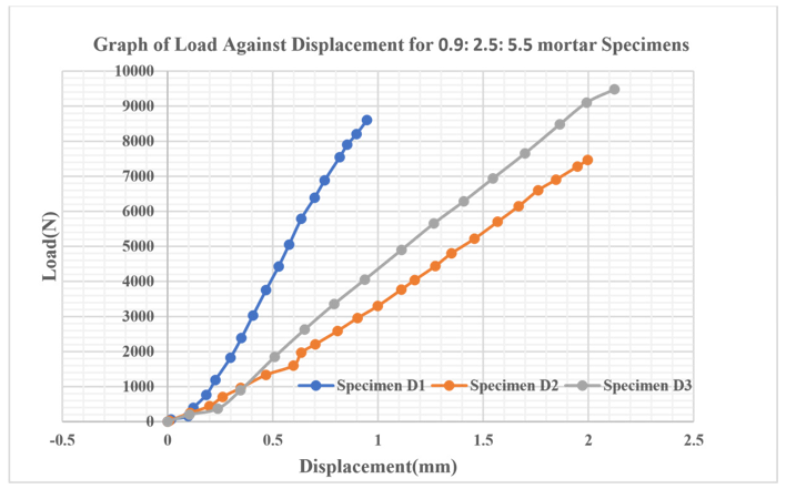
Figure 5: Load Against Displacement for Water: Cement: Sand Ratio of 0.9: 2.5: 5.5 for Specimen D1, D2 and D3 Under Direct Tensile Test
|
water: cement: sand ratio |
Specimen tag |
Ultimate tensile Strength (MPa) |
|
0.5:1:4 |
C1 |
1.7341 |
|
0.5:1:4 |
C2 |
2.2647 |
|
0.5:1:4 |
C3 |
1.6156 |
|
0.9:2.5:5.5 |
D1 |
3.1668 |
|
0.9:2.5:5.5 |
D2 |
2.9414 |
|
0.9:2.5:5.5 |
D3 |
3.8111 |
Table 2: The Ultimate Strength Values for the Specimen Under Direct Tensile Test
|
water: cement: sand ratio |
Specimen tag |
Ultimate tensile Strength (MPa) |
|
(MPa) |
tensile |
Strength |
|
0.5:1:4 |
K1 |
1.15817 |
|
0.5:1:4 |
K2 |
1.22988 |
|
0.5:1:4 |
K3 |
1.167781 |
|
0.9:2.5:5.5 |
M1 |
1.43339 |
|
0.9:2.5:5.5 |
M2 |
1.40018 |
|
0.9:2.5:5.5 |
M3 |
1.39332 |
Table 3: The Ultimate Strength Values for the Specimen Under Split Test (Indirect Tensile Test)
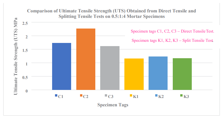
Figure 6: Comparison of Ultimate Tensile Strength (UTS) Obtained from Direct Tensile and Splitting Tensile Tests on 0.5:1:4 Mortar Specimens
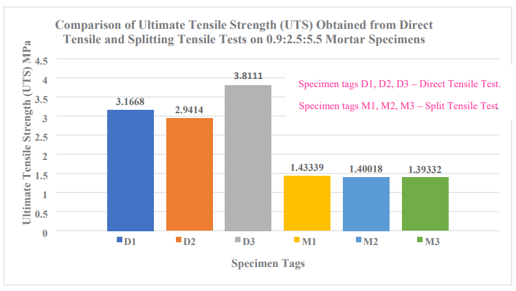
Figure 7: Comparison of Ultimate Tensile Strength (UTS) Obtained from Direct Tensile and Splitting Tensile Tests on 0.9:2.5:5.5 Mortar Specimens
Conclusion
Based on the analysis, it is concluded that the developed direct tensile test method was effective in guaranteeing that each mortar specimen fractured in the middle as expected when direct tensile test is carried out on a specimen. Proper gripping technique developed ensured that none of the specimen under direct tensile test slipped during the tests vindicating the implementation of the designed steel rigs, KAPCI polyester car-body filler combined with dibenzoyl peroxide hardener, and the clamps used for secure gripping of the specimen. Under uniaxial tension, all examined specimens exhibited non-linear elastic behavior, as there is no distinct transition from elastic to plastic deformation before failure, a phenomenon also observed in cement paste and mortar with a water-cement ratio of 0.5, as noted by [14]. There was a significant increase in strength in all the specimen tested under 0.9:2.5:5.5 mortar mixture ratio compared to 0.5:1:4 mortart mixture ratio. This further affirmed that decrease in water to cement ratio signifucantly improves mortar strength. These findings demonstrate that the strength of a mortar can be accurately determined using the direct test suggested in this study. This study is meant to improve the reliability of the Tensile tests done for mortar mixtures used in construction industries and to acertain the accuaracy of the results obtained from these tests.
Recommendation and Future Studies
We would recommend numerical simulations of the mortar mixture ratios used in this study and the simulation results to be compared with these ones presented here to acertain their reliability, accuracy and the techniques used during this study's experiments. We further recommend other researchers in Materials science and composites field to recommend or suggest a standardized adhesive that is universal and be used alongside the suggested steel rig for proper specimen alignment and clamping during direct tensile tests.
References
- Venkatesan, P. V., Suganya, R., & Revathi, S. (2022). Experimental investigations on concrete incorporated with calcined hydrotalcite under sea water curing. Materials Today: Proceedings, 62, 4374-4378.
- Ramakrishna, G., & Sundararajan, T. (2019). A novel approach to rheological and impact strength of fibre-reinforced cement/cementitious composites for durability evaluation. In Durability and Life Prediction in Biocomposites, Fibre-Reinforced Composites and Hybrid Composites (pp. 389-406). Woodhead Publishing.
- Aziam, R. (2022). Equilibrium and Thermodynamic Studies for the Removal of Anionic Congo Red Dye by Carpobrotus Edulis Plant as Low-Cost Biomaterial. Journal of Material Sciences & Manufacturing Research, 1–7.
- Lanas, J., & Alvarez-Galindo, J. I. (2003). Masonry repair lime-based mortars: factors affecting the mechanical behavior. Cement and concrete research, 33(11), 1867-1876.
- Parisi, F., Menna, C., & Prota, A. (2019). Fabric-reinforced cementitious matrix (FRCM) composites: Mechanical behavior and application to masonry walls. Failure analysis in biocomposites, fibre-reinforced composites and hybrid composites, 199-227.
- Mujalli, M. A., Dirar, S., Mushtaha, E., Hussien, A., & Maksoud, A. (2022). Evaluation of the tensile characteristics and bond behaviour of steel fibre-reinforced concrete: An overview. Fibers, 10(12), 104.
- Dhir, R. K., de Brito, J., Silva, R. V., & Lye, C. Q. (2019). 12 -Use of Recycled Aggregates in Road Pavement Applications, in Sustainable Construction Materials, R. K. Dhir, J. de Brito,R. V Silva, and C. Q. Lye, Eds., in Woodhead Publishing Series in Civil and Structural Engineering. Woodhead Publishing, 451–494.
- Wang, T., Xiao, F., Amirkhanian, S., Huang, W., & Zheng,M. (2017). A review on low temperature performances of rubberized asphalt materials. Construction and Building Materials, 145, 483-505.
- Matysek, P., Serega, S., & Kanka, S. (2017). Determination of the mortar strength using double punch testing. Procedia engineering, 193, 104-111.
- Carpinteri, A., & Maradei, F. (1995). Three-jack solution to obtain a truly stable and symmetric tensile concrete test. Experimental mechanics, 35(1), 19-23.
- Alhussainy, F., Hasan, H. A., Sheikh, M. N., & Hadi, M. N. (2019). A new method for direct tensile testing of concrete. Journal of Testing and Evaluation, 47(2), 704-718.
- Swaddiwudhipong, S., Lu, H. R., & Wee, T. H. (2003). Direct tension test and tensile strain capacity of concrete at early age. Cement and concrete research, 33(12), 2077-2084.
- Liao, W. C., Chen, P. S., Hung, C. W., & Wagh, S. K. (2020).An innovative test method for tensile strength of concrete by applying the strut-and-tie methodology. Materials, 13(12), 2776.
- Rashmi, S. M., Rajesh Kumar, K., Akki, B., & Rajasri Reddy,I. (2020, December). Performance Studies on white topping layers over flexible pavement. In IOP Conference Series: Materials Science and Engineering (Vol. 981, No. 3, p. 032076). IOP Publishing.
- Carmona, S., & Aguado, A. (2012). New model for the indirect determination of the tensile stress–strain curve of concrete by means of the Brazilian test. Materials and structures, 45(10), 1473-1485.