

Advances in Theoretical & Computational Physics(ATCP)
ISSN: 2639-0108 | DOI: 10.33140/ATCP

Review Article - (2026) Volume 9, Issue 3
Understanding Magnetic Hose

Received Date: Jul 16, 2026 / Accepted Date: Aug 27, 2026 / Published Date: Aug 31, 2026
Copyright: ©2026 Abhijit Bhattacharyya. This is an open-access article distributed under the terms of the Creative Commons Attribution License, which permits unrestricted use, distribution, and reproduction in any medium, provided the original author and source are credited.
Citation: Bhattacharyya, A. (2026). Understanding Magnetic Hose. Adv Theo Comp Phy, 9(3), 01-09.
Abstract
Fast magnetic flux control is important for circuit quantum electrodynamics (cQED) to control qubit precisely. The 3D superconducting microwave resonators posses higher volumes turning them to insensitive to surface dielectric losses resulting in higher Q values in comparison to 2D resonators which have higher dissipation due to surface losses. Thus 3D resonators increase the decoherence time. Although this makes a strong reason to opt for 3D superconducting resonators while it is difficult to tune the qubit using fast magnetic field accurately from outside the 3D resonator. In this paper, we try to understand transporting the magnetic filed inside a cylindrical superconducting cavity implementing a cylindrical magnetic hose using finite element analysis.
Keywords
Magnetic Field, Metamaterial, Flux Tuning, FEA, Comsol, Superconducting Cavity
Introduction
Reliable quantum control with scalability of number of qubits in operation simultaneously demand conditional, time-dependent Hamiltonian. The objective of the operation is control, selectivity and scalability. Fast flux modulation enables time-dependent control of the Hamiltonian H(t)≠ constant with high fidelity. Here fast means faster than the decoherence time of the qubit in operation.
To understand, let us consider two qubits and then apply CZ gate (controlled phase gate). The CZ gate is a Clifford gate (also symmetric) can flip the phase of the target qubit if the control qubit is in the |1⟩ state. This gate can operate in non-adiabetic way using fast pulse tuning technique. If they interact continuously, errors will accumulate due to crosstalk and idle errors. Therefore, fast flux tuning would enable need based strong interaction. There will be no interaction otherwise resting those two qubits as de-tuned (i.e. safe idle) completing the full operation within 10−70 ns. In the scaled up scenario, fast tuning provides dynamic avoidance of frequency collisions and post fabrication calibration while modulating qubit frequency at a chosen tone through parametric modulation activating interactions like iswap, bswap etc.
Superconducting cavities of type 2D· coplanar plane wave (CPW) and/or 3D· cavities are used to exchange photons to provide energy to the qubit or read it. However, the interaction between a qubit and cavity are not fully efficient in driving or reading due to facts like interaction losses or low quality factors (Q values). Qubits decay down to the ground state from excited state by the decoherence. While qubit of exceptional manufacturing qualities are essential, use of 3D· superconducting resonators enhance the coherence due to exceptionally high Q-values in the microwave domain [1-4]. The cavities are made up of superconducting materials to posses high Q values while the walls perfectly shield the external magnetic field following the Meissner effect.
This creates problem for the magnetic flux tuning of the qubit from outside the cavities. There is also another issue. The quantum circuits are kept within the cavity means the circuit does not directly gets coupled to the cold plate of the dilution refrigerator causing increase of thermal noise. These makes transferring the magnetic field a challenge to use 3D· cavities even when appreciating its high Q values. Time-varying magnetic fields induce large, lossy screening currents and excite cavity modes across the entire superconducting enclosure destroying high-Q environment. Many studies have been done in this regard like frequency tunable magnetostatic wave filters, understanding optically pumped magnetometer with high spatial magnetic guide, on demand transposition across light matter interaction in bosonic cQED [5-7].
It is common practice to select Aluminium (Al) and Niobium (Nb) for fabrication of 2D or 3D· resonators. Aluminium is a type-I superconductor having critical field Hc ≈ 0.0105Tmeans all the magnetic field gets expelled below this field while superconductivity is destroyed above this field [8-10]. Niobium, on the other hand, is a type-II superconductor possessing two critical field limits between which "Mixed state" exists comprising superconducting and normal state. The lower critical field for Niobium is at Hc1 ≈ 0.17T . Below Hc1, Niobium is a perfect superconductor like Aluminium. The upper critical field is at ≈ 0.24t above which superconductivity is completely lost [11]. However, these indicative values are for highly pure and strain free crystals of Niobium. In "dirty" niobium (containing impurities or physical defects), Hc2 can rise significantly (up to ∼ 0.4t ) as impurities pin magnetic flux lines allowing the material to withstand higher fields. It is good to operate under 0.15T to keep Niobium in good superconducting state. It is clear that transporting the magnetic field inside a 3D· resonator is a challenge. One of the ways to transport the magnetic field is using the magnetic hose - a sort of meta-material.
The objective of this study is to get ideas on the engineering constraints for a cylindrical resonator and cylindrical magnetic hose transporting magnetic fields using finite element method. using the COMSOL finite element software, we construct geometric model of a superconducting resonator containing a cylindrical magnetic hose [12,13]. Magnetic field is generated outside the resonator using a coil. We also discus analytical field transport efficiency following so that we may get parameter limits for construction of the magnetic hose [14].
Design Modeling
Concept
To resolve the magnetic field issue inside the super conducting cavity, one may consider keeping the magnetic source inside the superconducting cavity or may consider guiding the magetic field from external source to the resonator. If the magnetic source is kept inside the cavity and cooling down phase starts, magnetic field never vanish but gets trapped within the cavity walls of finite thickness as quantized filaments called as Abrikosov Vortices or fluxons [15, 16]. These vortices are defects in the superconducting state — tiny tornadoes of "normal" (non-superconducting) material that pierce the cavity wall, acting as resistive hotspots degrading the cavity performance Q-factor by dissipating RF energy as heat. A good number of studies have been done above 1K while worked in the milli-kelvin (10 mK) and low-photon regime. This study reported vortex-induced degradation of T 1 - longitudinal relaxation time.
It is interesting to note that the time-dependent electromagnetic fields, can be transmitted and routed to long distances using wave guides. This method is not applicable for the transfer static magnetic fields. Static magnetic field can be transported by ferromagnetic materials with high magnetic permeability (µ) analogous to transferring magnetic field from primary to secondary circuit in a transformer [17,18]. Guiding the magnetic field to arbitrary long distance has been discussed in [14]. The main issue is the rapid decay of the transferred field over a large distance.
It is demonstrated in [14] that the medium to transfer the field having isotropic permeability (µ) yields high values of magnetic flux density B not only in the direction of the cylinder axis Z but also in the radial direction, so that the field escapes through the cylinder lateral surface and the value at its end decreases drastically with increasing length. If magnetic field is guided through a hollow superconducting cylindrical pipe, the transferred field may rapidly decrease with increasing the tube length [19].
Therefore the requirement is some sort of magnetic field transportation device that may operate at miili-kelvin regime designed to solve the paradox of guiding a static magnetic field without destroying superconducting state of the cavity. While superconductor expels magnetic fields (Meissner effect), this transportation device will act as a shielded tunnel delivering precise magnetic flux to a target (e.g., a Qubit) inside the cavity while keeping the rest of the environment magnetically silent using the principles of transformation optics [20- 23].
The principle is to consider a material possessing very low permeability in the radial direction (µr → 0) showing perfectly diamagnetic behavior radially while very high permeability in the azimuthal and vertical direction ( → ∞, µz → ∞) showing ferromagnetic behavior. As there is no single natural material possessing that property, a composite material using a superconductor and a ferromagnetic material is engineered as a meta material. The engineered product is called as "Magnetic Hose" to transport the magnetic field. The effective permeability µeff of the product will be an anisotropic permeability tensor. Meta materials made up of a series of alternating layers of superconducting paramagnetic material like aluminium and ferromagnetic material like µ-metal may be used to guide static magnetic flux as magnetic hose [24]. The magnetic hose efficiently guide static magnetic flux, suppresses lateral field leakages and does not guide microwave magnetic fields keeping superconducting resonator intact.
The magnetic hose transports magnetic field pulses as Low Pass filter blocking high frequency noises, thus preventing thermal noise to pass through the hose preventing qubit relaxation due to high frequency thermal noise. A magnetic hose can not tune a fast flux but can transfer flux quantum. Fast flux tuning basically needs a flux-sensitive element like a SQUID, a fast current source or a bias line as either on-chip or as very low-inductance line and a suitable methodology to deliver the fast flux without degrading the cavity. Magnetic field changes in superconducting cavity inducing screening currents that flow within a thin surface layer - London P

Figure 1: Efficiency of Magnetic Flux Transfer Axially and Also Effect of Layer Numbers.
The magnetic hose affects both SQUID and non-SQUID transmon, but in different ways. A SQUID couples to magnetic flux through loop interference while a non-SQUID transmon couples only to magnetic field utilizing pair-breaking and kinetic inductance. This is achieved by using high μ ferromagnets like μ-metal or metglas to pull and concentrate DC magnetic flux while at the same time using superconducting material like aluminium to expel transverse magnetic field using the Meissner effect.
Let us consider a cylindrical magnetic hose to transport magnetic field vertically or axially without any loss in radial direction. Hence, the radial permeability must behave as a series circuit resisting passage of the magnetic field. Since our intended product is a composite material, we need to consider volume fraction. Let fF and fs be volume fraction of ferromagnetic and superconducting material in the composite product which may be computed from the ratio of thickness of the material like ferromagnetic or superconductor to the total thickness of the magnetic hose. The radial component of the effective permeability will be

As µs→ 0, superconducting contribution dominates resulting in µreff → 0. Therefore magnetic field will not leak radially.
The azimuthal and axial or vertical components of the effective permeability components reduce to
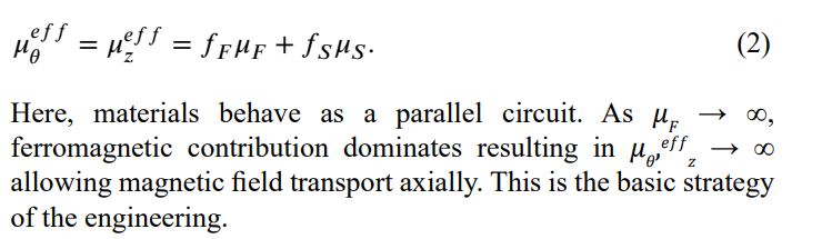
The equations (1, 2) demonstrated that the anisotropic permeability tensor of the composite material creates a "topological tunnel". To the external environment (the Niobium cavity), the hose looks like a superconductor (µr ≈ 0), so it does not perturb the Meissner state of the cavity. To the magnetic field inside the hose, it looks like a ferromagnet (µz ≈ ∞), allowing the flux to travel freely to the qubit. The equations (1, 2) demonstrated that the anisotropic permeability tensor of the composite material creates a "topological tunnel". To the external environment (the Niobium cavity), the hose looks like a superconductor (µr ≈ 0), so it does not perturb the Meissner state of the cavity. To the magnetic field inside the hose, it looks like a ferromagnet (µr∞), allowing the flux to travel freely to the qubit. c transfer axially and also its dependence on the number of layers of composite material as shown in figure (1). It is clear that the efficiency of the transfer reduces if axial distance increases.Similarly, efficiency saturates after a certain number of layers which guides effective engineering.

(a) Geometry of The Setup. Air Block Is Kept Hidden to Reveal the Other Objects.
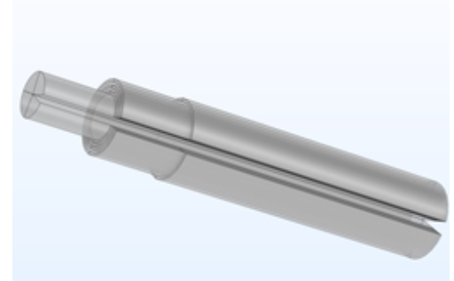
(b) The Magnetic Hose with A Vertical Cut
Model and Design
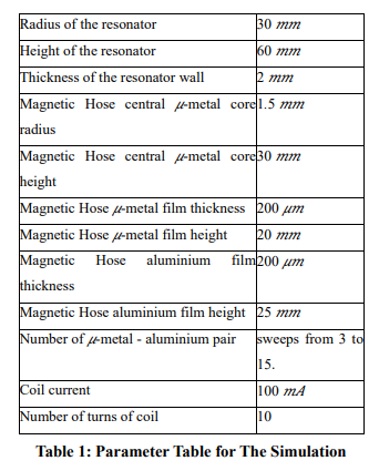
The design criterion of the magnetic hose requires magnetic field transfer without allowing surface eddy current flow. In this study, a cylindrical resonator as in figure (2a) is considered containing a cylindrical magnetic hose as in figure (2b) to realize the effect of meta material using finite element method (FEM). Here we have chosen Niobium resonator figure (2a). The distribution of magnetic field may be studied using the Magnetic field (mf) sub-module in the AC\DCmodule of the COMSOL software. Zhang et al also reported study of magnetic flux concentrators by finite element method for designing hose plates [25]. We present here pure computer simulation procedure for design optimization. We consider a cylindrical Niobium resonator placed above an electrical coil carrying current as shown in the figure (2a). The specifications have been described in the table 1. To make the magnetic hose, we take aluminium and µ metal films in alternate fashion wrapped around the central core pin.
A central core pin of µ-metal is taken around which aluminium and µ-metal sheets are wrapped alternately as may be seen in the figure (2b). Operating at sub-kelvin temperature, aluminium becomes superconducting. The high surface current due to super-current flowing in aluminium will cause huge loss of energy due to eddy current flow. To stop the loss, the hose is cut vertically to make a notch stopping surface current.
Simulation and Result
To simulate magnetic fields sub-module in ACDC module is considered where current coil is designed in this sub-module separately mentioning coil parameters and input current surface etc. The coil can be meshed with swept meshing. The resonator and outside air boundary may not need fine meshing. The aluminium and µ-metal sheets may be meshed separately mentioning minimum and maximum element sizes. Central pin needs separate meshing. If meshing is not done properly resulting may show some singularities


(a) Magnetic Field Distribution Using the Stationary Study. (b) Flow of Azimuthal Current Through the Coil.
Figure 3: Magnetic Field (Normalized) and Coil Current
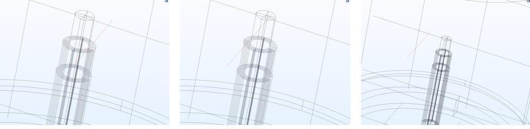
Figure 4: Different Cut Lines to Extract Data Including One on The Top of The Core Pin.
If memory is available, one may choose simple normal mesh to go through the first few runs of simulation to check validity, convergences etc.
We start the simulation for stationary study using 3 pairs of sheets (µ-metal-aluminium pair) and in the sweep mode, we vary number of pairs between 3 and 15. The reason for choosing upto 15 may be inferred from the figure(1) which showed that after around 15 or so, the efficiency nearly reaches saturation.
Initially, we consider only three µ metal-aluminium pairs. Figure (3a) shows the magnetic field distribution due to flow of current in the coil. Figure (3b) shows the flow of azimuthal current through the coil. We are interested to evaluate µ at certain height near the top of the magnetic hose. So we draw some cut line for the datasets at different places like above the central pin of the hose, above the aluminium sheets over the notch and on the opposite of the notch so that results may reveal the notch effect.
Figures in (4) show three cut lines - on the top of the central core, on the aluminium above the notch and on the aluminium opposite to the notch. The field data extracted on those lines may provide an insight of the transfer efficiency. Figure (5) shows the most important indication that the field outside the hose area is very less clearly showing the purpose of the hose to transport the static magnetic field is established. Next important information is hose effectively transports the field while the notch area cut to limit the super-current eddy shows a slight dip. If a qubit chip is introduced inside this setup, the qubit must be parallel to the field.
However, The objective to understand the working principle of the magnetic hose to transport the magnetic field is established. we need to establish the number of pair of aluminium and µ-metal considering the efficiency study from the first principle as seen in the figure (1). Therefore, we study sweeping the pair numbers between 3 and 15.
Like before we need to extract data at specific locations. So we select zone above the central pin and see the field data as seen in figure(6). The figures shows a dip in central pin area of 3 mm span while sharp rise on both sides. Next we select two lines on the hose to measure the magnetic field - one on the notch and the other on the opposite side as shown in figures (7a, 8a).

Figure 5: Mapping of B z at Different Locations on Same Heights Radially
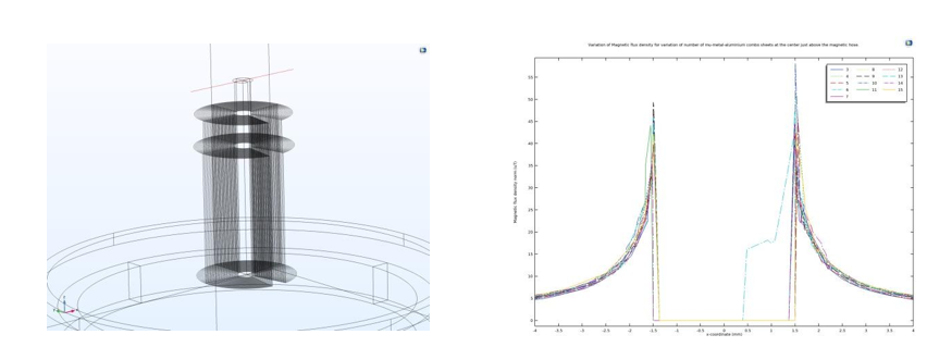
(a) The Cut Line to Extract the Data for Figure(6b) (b) Bz on the Cut Line Shown in Figure (6a)
Figure 6: Bz measured Above the Central Core Pin. Parameters are Number of Sheet Pairs.
Figure (7b) also clearly depicts the dip at the notch area. There are also some other observations. The simulation shows maximum peak field may be achieved by 3 sheet pairs while it provides a narrow region to transport the field. This means the qubit circuit needs to be placed in that narrow zone. Other higher number of pairs have larger span while lesser peak value. Beside this, larger number of sheets show ringing effect due to other µ-metal sheets.


(a) The Cut Line Above Aluminium Sheet on The Notch. (b) Magnetic Field Above the Hose on The Cut.
Figure 7: The Data is Above the Aluminium Film on The Notch Showing A Dip. Parameters are Number of Sheet Pairs
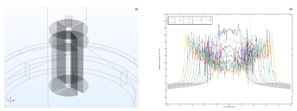
(a) The Cut Line is Not on The Notch. (b) Bz Above the Hose Not on The Cut.
Figure 8: Bz Above the Aluminium Film Opposite to The Cut Side. Parameters are Number of Sheet Pairs
Figure (8b) also shows features similar to the figure (7b) while differing only in the central dip as figure (8a) is on the opposite side of the notch. We see the Butterfly Effect in the field distribution against the sheet numbers. The ringing effect can also be used to place the qubit circuit for chosen magnetic field value. Figure (9) shows field measured a bit away from the hose on the line shown in figure (9a). The last layer outside the hose is µ-metal. The increase of field at the central region may be due to the effect of the last ðÂÂ??-metal sheet. The maximum field value is for sheet number 15.
However, this design comes with a note on the saturation limit of transfer of the magnetic field. To maintain high permeability, mu-metal must be annealed in a hydrogen atmosphere after fabrication to remove stresses. The critical field guides the limit of magnetic field transfer for the magnetic field as discussed earlier. The maximum transferable limit of the magnetic flux is limited by the saturation flux density (≤ Bs) of the core material which for mu-metal is about Bs ≤ 0.8T [26]. The reluctance drops sharply as the field increases. A 1 mm thick annealed mu-metal layer can reduce stray fields down to below a 0.1 nT level.
Conclusion
The simulation established the validity of the concept and optimum engineering requirement for the number of the sheets.The thickness of the sheet considered comes from our manufacturing limit without modification of the equipment. This simulation study provides a framework for further understanding. We are preparing report on the effect of using hose close to the periphery of the resonator besides other topologically different shapes.


(a) The Cut Line is Outside The Hose Area. (b) Magnetic Field Away from The Hose.
Figure 9: Bz Measured Out of Hose Area Keeping Same Height as Above. Parameters are Number of Sheet Pairs
Author Contributions: The author is solely responsible for the conceptualization, methodology, simulation, validation, analysis, draft preparation, writing—review and editing, visualization.
Funding: This research did not receive any specific grant from funding agencies in the public, commercial, or not-forprofit sectors.
Data availability: The python code for computing the efficiency and the comsol code for the simulation is available to the author and may be obtained upon request.
Conflicts of Interest: The author declares no conflict of interest.
References
- Paik, H., Schuster, D. I., Bishop, L. S., Kirchmair, G., Catelani, G., et al. (2011). Observation of high coherence in Josephson junction qubits measured in a three-dimensional circuit QED architecture. Physical Review Letters, 107(24), 240501.
- Wang, X. L., Hao, G. D., & Toda, N. (2015). Controlling the directionality of spontaneous emission by evanescent wave coupling. Applied Physics Letters, 107(13).
- Reagor, M., Paik, H., Catelani, G., Sun, L., Axline, C., Holland, E., ... & Schoelkopf, R. J. (2013). Reaching 10 ms single photon lifetimes for superconducting aluminum cavities. Applied Physics Letters, 102(19).
- Reshitnyk, Y., Jerger, M., & Fedorov, A. (2016). 3D microwave cavity with magnetic flux control and enhanced quality factor. EPJ Quantum Technology, 3(1), 13.
- Du, X., Idjadi, M. H., Ding, Y., Zhang, T., Geers, A. J., et al. (2024). Frequency tunable magnetostatic wave filters with zero static power magnetic biasing circuitry. Nature Communications, 15(1), 3582.
- Jofre, M., Romeu, J., & Jofre-Roca, L. (2023). Optically pumped magnetometer with high spatial resolution magnetic guide for the detection of magnetic droplets in a microfluidic channel. New Journal of Physics, 25(1), 013028.
- Valadares, F., Huang, N.-N., Chu, K. T. N., Dorogov, A.,Chua, W., et al. (2024). On-demand transposition across light-matter interaction regimes in bosonic cQED. Nature Communications, 15, 5816.
- de Gennes, P. G. (2018). Superconductivity of metals and alloys. CRC Press.
- Tinkham, M. (2004). Introduction to superconductivity (2nd ed.). Dover Publications.
- Harris, E. P., & Mapother, D. E. (1968). Critical field of superconducting aluminum as a function of pressure and temperature above 0.3 K. Physical Review, 165(2), 319–325.
- Ono, M., Kako, E., et al. (1999). Magnetic field effects on superconducting cavity. In Proceedings of the 1999 Workshop on RF Superconductivity. JACoW.
- COMSOL. (2021). AC/DC Module User’s Guide: COMSOL Multiphysics version 6.1. COMSOL.
- Walter, F. (2020). Course modeling: Electromagnetic coils in COMSOL. COMSOL.
- Navau, C., Prat-Camps, J., Romero-Isart, O., Cirac, J. I., & Sanchez, A. (2014). Long-distance transfer and routing of static magnetic fields. Physical Review Letters, 112(25), 253901.
- Bafia, D., Abdisatarov, B., et al. (2026). Quantifying trapped magnetic vortex losses in niobium resonators at mK temperatures. arXiv.
- Posen, S., Checchin, M., Melnychuk, O. S., Ring, T., Gonin, I., et al. (2023). High-quality-factor superconducting cavities in tesla-scale magnetic fields for dark-matter searches. Physical Review Applied, 20(3), 034004.
- Jackson, J. D. (1999). Classical electrodynamics (3rd ed.).Wiley.
- Coey, J. M. D. (2010). Magnetism and magnetic materials. Cambridge University Press.
- Levin, Y., & Rizzato, F. B. (2006). Superconducting pipes and levitating magnets. Physical Review E, 74.
- Chen, H., Chan, C. T., & Sheng, P. (2010). Transformation optics and metamaterials. Nature Materials, 9, 387–396.
- Pendry, J. B., Schurig, D., & Smith, D. R. (2006). Controlling electromagnetic fields. Science, 312(5781), 1780–1782.
- Pendry, J. B., Aubry, A., Smith, D. R., & Maier, S. A. (2012). Transformation optics and subwavelength control of light. Science, 337(6094), 549–552.
- Ward, A. J., & Pendry, J. B. (1996). Refraction and geometry in Maxwell's equations. Journal of Modern Optics, 43(4), 773–793.
- Gargiulo, O., Oleschko, S., et al. (2021). Fast flux control of 3D transmon qubits using a magnetic hose. Applied Physics Letters, 118.
- Zhang, X., Bi, Y., et al. (2018). Influence of size parameters and magnetic field intensity upon the amplification characteristics of magnetic flux concentrators. AIP Advances, 8.
- Arpaia, P., Burrows, P. N., Buzio, M., Gohil, C., Pentella, M., et al. (2021). Magnetic characterization of Mumetal® for passive shielding of stray fields down to the nano-Tesla level. Nuclear Instruments and Methods in Physics Research Section A: Accelerators, Spectrometers, Detectors and Associated Equipment, 988, 164904.