
Archivos de Ciencia e Investigación(ADCI)
ISSN: 3068-014X | DOI: 10.33140/ADCI


Research Article - (2025) Volume 1, Issue 2
Study of the Clogging Phenomenon of Submerged Nozzles in Continuous Casting
Received Date: Aug 28, 2025 / Accepted Date: Sep 29, 2025 / Published Date: Oct 27, 2025
Copyright: ©©2025 Firas Mekhenache, et al. This is an open-access article distributed under the terms of the Creative Commons Attribution License, which permits unrestricted use, distribution, and reproduction in any medium, provided the original author and source are credited.
Citation: Mekhenache, F., Snani, L., Benchikha, T. (2025). Study of the Clogging Phenomenon of Submerged Nozzles in Continuous Casting. Arch Cienc Investig, 1(2), 01-10.
Abstract
The continuous casting nozzle which guides and protects the flow of liquid steel undergoes a progressive reduction in its internal diameter following the accumulation on the internal wall of non-metallic inclusions. This narrowing of the channel is due to a mechanical attachment (non-metallic inclusions) and this, because of the turbulent regime of the flow of the liquid steel. This phenomenon is very often associated with the casting of low carbon steels deoxidized exclusively with aluminum. Clogging generally leads to a slowing down of the casting speed and, in severe cases, to the total stoppage of the installation and consequently to the appearance in the slab of the defect called "resumption of casting or belt". The aim of this work is to determine the nature of the deposit and the blocking mechanism of the pouring nozzles. For that, a chemical analysis as well as tests concerning the adhesion of the deposit were carried out on samples taken from damaged pouring nozzles. We found that it was at a load of 187.5 kgf that the rupture of the sample took place, during the interfacial indentation tests, which represents a very high level of adhesion. On the other hand, chemical analysis by X-ray fluorescence of the deposits revealed a fairly high level of alumina (Al2O3 = 90%) which undoubtedly comes from inclusions resulting from the deoxidation of the metal. It can therefore be said that the clogging phenomenon is produced by a continuous attachment of non-metallic inclusions to the rough walls of the nozzle.
Keywords
Alumina, Clogging, Submerged Nozzle, Non-Metallic Inclusions, Continuous Casting, Adhesion, Roughness
Introduction
This work deals with the quality of mild steels intended for the manufacture of thin sheets to subsequently undergo tinning. It particularly concerns the prevention of the formation of quantities of non-metallic inclusions which could damage the quality of the metal [1]. Above all, if it is known that ultra-low carbon steel (low- er < 0.07%) is exclusively calmed by aluminum, and this because of the constraints due to the chemical composition, in fact, it is known that the calming of this type of steel is conventionally car- ried out in a ladle by adding aluminum, the reaction of which, with the oxygen present in the metal bath, produces aluminates which mainly settle on the surface of the liquid metal, first in a ladle and then in the dispatcher [2,3].
Unfortunately, some of these non-metallic inclusions remain in suspension within the liquid metal. In addition, it is known that the continuous casting of a semi-finished product with a large cross-section usually requires the use of a submerged nozzle to feed the mold. Moreover, it is known that these nozzles are subject to fattening, leading in the more or less long term to their total clogging and consequently to the immediate stoppage of the casting in progress, which affects the slab in the form of a defect called “returns of casting”. It should be pointed out that practically 64% of the castings produced at the oxygen steelworks (case studied) suffered nozzle clogging following the erosion of the internal wall [4,5].
In addition, it is known that it is the particles of non-metallic inclusions, remained in suspension which, while crossing the nozzle, cling to the wall of the tube and by accretion phenomenon cause over time the total blockage of the passage metal. The phenomenon has been the subject of several individual or collective studies in order to make these inclusions less harmful [6].
One of the peculiarities of the production of steel in the oxygen steelworks concerns blowing back due to a high content of manganese in the cast iron (Mn=2.36% on average) thus contributing strongly to the overoxidation of the metal. The production of steel always includes a refining phase in which the impurities contained in the cast iron are partially or totally burned using oxygen. The oxides formed pass into the slag, with the exception of carbon monoxide which escapes with the gas [7,8].
It has been demonstrated that among the factors which favor the solubility of oxygen in the liquid metal, the temperature is a very important element. Indeed, the increase in the temperature of the bath considerably increases the concentration of oxygen which, for example from [O] = 0.005% in the solid metal it goes to 0.23% in the liquid steel at the metallurgical temperature 1640°C.
The decrease in the carbon content in the liquid metal increases the activity of oxygen, hence the difficulty of deoxidizing ultra-low carbon steels (grade which is the subject of our research) which exclusively requires a large quantity of aluminum [9,10]. (This steel is intended for the manufacture of thin sheets).
The factors which favor the increase in the content of dissolved oxygen in the liquid metal are high temperature, low carbon concentration and high FeO content. Obviously, other factors can also have an influence such as hydrogen and nitrogen; but for the rest of our work, we will limit ourselves only to the most important in our opinion: carbon [11-14].
Recall that the steel production process at the oxygen steelworks (case studied) is distinguished by a large number of reblown castings for manganese not reached at the end of refining, which results in a significant increase in temperature, the amount of FeO, and carbon overoxidation. The blockages of the nozzles affect the quality of the slabs in the form of "belts" which can be defined as a discontinuity in cross section of the slab; Figure 1 shows a resumption of casting or belt in the slab [15].

Figure 1: Slab with Belt
Materials & Methods
Location and Morphology of the Deposit
The localization of the deposit having blocked the nozzle was carried out by observation with the naked eye;
The morphological identification of the deposit consists of observing a sample using a binocular magnifying glass. The sample was cut from the lower part and cut by an ordinary chainsaw, and then we detached the metal envelope, as well as the terminal deposit and leaving only the dense deposit which adheres to the refractory body of the nozzle. Figure 2 shows clogged worn nozzle.

(1)clogged nozzle body, (2) white deposit (3) metal casing.
Figure 2: View of a Clogged Worn Nozzle
Figure 3 Indicates Cross Section of a Submerged Nozzle
View of a cross section of the lower part of a nozzle
Figure 3: Cross section of a submerged nozzle
Chemical Characterization of Deposit
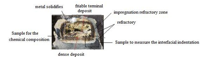
After the macromorphological identification of the deposit, we took a sample from each zone as shown in the diagram. The chemical composition is carried out by x-ray fluorescence and to determine the concentration of chemical elements and or metal oxides, as it gives a more precise measurement. The metal casing and the deposit of the lower part of the nozzle are made up of a mixture of slag from the converter and metal oxides resulting from deoxidation, Figure 4 indicates Layout diagram of the different layers.

Figure 4: Layout diagram of the different layers
The taking of the samples of the deposit to carry out the chemical composition is carried out by a chainsaw, then to take off the dense deposit (C), from the impregnated refractory zone (B), we used a hammer and a chisel, then in the same way we separated the affected refractory zone (B) from the healthy refractory (A). Figure 5 explains materials obtained after separation.

(A) Refractory zone (B) Affected zone (impregnation) (C) Dense deposit (D) Terminal sintereddeposit
Figure 5: Materials obtained after separation.
We crushed these materials to obtain fine powders with a particle size of approximately 5 to 15μm to produce pellets after fusion in order to carry out chemical analysis using X-ray fluorescence.
Adhesion Test
Interfacial Indentation (Refractory / Deposit)
To prepare our samples, we recovered a used nozzle which we cut in the transverse direction of Figure 4. To study the adhesion of the dense deposit (C) on the body of the nozzle we cut samples from the lower part, we removed the terminal deposit (D) which has very weak and friable mechanical properties, finally we completed cutting with a manual chainsaw.
Subsequently, we cut these samples with the Mécatome TZ 10 type micro-cutting machine, until a flat and uniform sample was obtained and, because of its low thickness (3 to 5 mm), this sample was coated with epoxy as shown in Figure 6 samples prepared to measure interfacial indentation .

Figure 6: Samples Prepared to Measure Interfacial Indentation.
To perform the interfacial indentation, we used a Vickers micro- hardness tester, a Vickers hardness tester, and finally a Rockwell hardness tester until the part was destroyed. Figure 7 explains de- termination of the nature of the break

Figure 7: Determination of the nature of the Break.
After the interfacial indentation, we marked a point using a wire cross on the two internal faces of the sample to determine exactly the chemical composition by EDS of the two opposite points.
Influence of the Preheating of the Nozzles on the Roughness of the Internal Wall of the Nozzle
a. Laboratory Experimental Setup
We have studied the influence of preheating new nozzles at a fairly low temperature (750°C), for variable heating times in an uncontrolled atmosphere. We carried out an experimental assembly which consists of a bracket to hold the nozzle, a natural gas burner and an ordinary pyrometer for temperature control Figure 8 shows nozzle experimental.

Figure 8: Experimental setup.
b.Nozzle Heating Sequence at the Factory
The heating time from the nozzle to the surface is 8 hours and more in some cases, the burner is oriented towards the bottom of the nozzle which undergoes intense heating over 1000°C while the top remains relatively cold, knowing that refractories are poor conductors of heat, this temperature difference causes the surface to burst, the consequence of which is spalling Figure 9shows sample nozzle view after heating.

Figure 9: View of a sample of a nozzle after heating at the steelworks.
c. Roughness Test
For the measurement of the roughness, we used a 2D roughness meter of the Sypertechnologie type. We took three samples that we cut and heated at a constant temperature of 750°C for periods of 45, 75 and 120 min, to determine the influence of temperature and heating time on roughness.
Presentation of Results
Observation of the Deposit with the Naked Eyeof the Clogged Nozzle
The lower part is almost completely clogged by a deposit, while the deposit in the upper part only measures a few millimeters; The deposit formed on the inner wall of the lower part can be divided into three layers:
-A gray metallic envelope.
-Layer of slag having a thickness comparable to that of the deposit formed on the upper part.
-An extremely thick deposit, several centimeters long with a crumbly appearance, in the form of a powder stuck to another white deposit, denser and less thick.
Binocular Observation
The observation of the deposit was carried out using an Optika digital binocular loupe, the photos of the different samples with an enlargement of 200 µm ,Figure 10 Binocular observation of the deposit.

Figure 10: Binocular observation of the deposit.
The results obtained are contained in Table 1.
|
Sample Number of Layer |
Layer Colors |
Odds |
Actual Odds |
Total Dimension |
|
|
|
|
|
(mm) |
µm |
(µm) |
|
Sample 1 |
3 |
Grey |
6 |
3000 |
5000 |
|
|
|
Chestnut |
1 |
500 |
|
|
|
|
White |
3 |
1500 |
|
|
Sample 2 |
2 |
Light grey |
4.5 |
2812.5 |
9062.5 |
|
|
|
White with gray spots |
7 |
6250 |
|
|
|
|
Grey |
0.6 |
300 |
|
|
Sample3 |
2 |
Brown with white spots |
0.4 |
200 |
500 |
Table 1. number, color, and thickness of the different deposit layers of the three samples
From these results, we can say that:
In addition to the layer separated before the observation and the dense deposit adhered to our samples, we detected a third layer of refractory origin according to its macroscopic morphology and its color;
After these observations, the new configuration of the deposit layers then becomes included inside the healthy zone according to the following order:
First zone: is the decarburized zone called the impregnation zone, its thickness is between [300; 3000] µm;
Second zone: is the dense deposit zone, white color with dark brown spots and light brown spots. Its thickness is between [200; 6250] µm;
Third zone friable terminal deposit: a very thick and very friable layer.
Chemical Analysis of Deposit and Refractory Part
The comparison of the results obtained with analyzes of the chemical compositions of the slag, the repair cement, and the gunning of the tundish. To study the evolution of the composition of the sound refractory (sample A), as well as the composition of the impregnation layer (sample B), we stuck to the chemical composition of new nozzle refractory.
In the figure, we have divided our nozzle profile into two parts according to the nature of the base materials (refractory or steel), the results obtained after chemical analyzes by X-ray fluorescence are collated in Table 2, namely:
• Refractory: it comprises the zone of sound refractory (A), as well as the zone of the layer of refractory affected by impregnation (B);
• Deposit: it comprises the dense deposit (C) as well as the terminal sintered deposit (D).
For more, we took by convention the names of the samples by following the direction which starts from the healthy refractory towards the terminal deposit and the flow channel of liquid steel, the results obtained after chemical analysis by fluorescence RX are gathered in the Table 2.
|
Sample No. |
Iron |
CaO |
SiO2 |
MgO |
Al2O3 |
MnO |
Cr2O3 |
K2O |
P2O5 |
Na2O |
SO3 |
TiO2 |
ZnO |
|
A |
34,091 |
1,968 |
1,080 |
0.931 |
61,032 |
0.510 |
0.045 |
0.048 |
0.198 |
0.062 |
0.001 |
0.031 |
0.003 |
|
B |
54,988 |
2,065 |
2,214 |
0.460 |
38,258 |
0.798 |
0.134 |
0.059 |
0.174 |
0.519 |
0.001 |
0.327 |
0.003 |
|
C |
40,262 |
0.728 |
3,419 |
0.246 |
53,348 |
0.399 |
0.064 |
0.043 |
0.175 |
0.353 |
0.001 |
0.961 |
0.001 |
|
D |
tracks |
tracks |
tracks |
tracks |
> 90 |
Tracks |
tracks |
Tracks |
tracks |
tracks |
tracks |
tracks |
tracks |
Table 2: Results of chemical analysis by Rx fluorescence
According to the chemical analyses, we found a very high quantity of iron of the order of 34%, with total decarburization; Table 3 represent chemical composition of nozzle, this result shows us that the decarburized or impregnation zone is more spread out and thicker.
|
Element |
Al2O3 |
SiO2 |
Graphite |
Na2O |
K2O |
MgO |
|
(%) |
66 |
9 |
24 |
0.5 |
0.06 |
0.44 |
Table 3: Chemical composition of the new nozzle
To facilitate the comparison, we have mentioned in Tables 4 and 5, the chemical analysis of slag, gunitage, cement, and chamotte bauxite.
|
Sample |
Iron |
CaO |
SiO2 |
MgO |
Al2O3 |
MnO |
P2O5 |
FeO |
|
% |
15.5 |
33.63 |
13.92 |
3.28 |
9.57 |
10.19 |
0.61 |
13.3 |
Table 4. Chemical analysis of the slag
|
Elements |
MgO |
CaO |
SiO2 |
Fe2O3 |
|
tundishgunning |
70 |
20 |
6.3 |
3.7 |
|
tundishrepaircement |
70 |
21 |
6 |
3 |
|
Bauxite chamotte from the nozzle |
44.5 |
52 |
3.5 |
/ |
Table 5. Chemical analysis of gunning products, tundish repair cement and bauxite chamotte from the nozzlerefractory
The results tell us about the nature of the deposit in general: The terminal deposit is mainly formed by Al2O3 with a percentage of 90%;
The dense deposit layer still remains predominant with an alumina percentage of 53.348%, followed by total iron with a percentage of 40.262%;
The affected refractory zone is a zone which has undergone a variation in the chemical composition. Indeed, the content of Al2O3 and that of SiO2 have dropped respectively: from 66% to 42.258%, and from 9% to 2.214%, we believe that this is due to the corrosion of our refractory material. We have also noticed that the iron content of 40.262% is very high; knowing that the initial iron content in the composition of the new nozzle is zero, so there is a great impregnation (diffusion of iron) in this layer. The impregna- tion in this zone is accompanied by a very intense affected, where we observed a null; We observe a significant increase in the iron content, in fact, it went from 15.5% to 54.98% in the affected area, as well as the significant decrease in the SiO2 and carbon content and that the impregnation layer is higher than the calculated thick- ness (tab III.1) this change in morphology as well as the variation in color, in fact, its color changed from metallic gray to light gray due to the increase in the alumina content (42% to 61%); Note that the tundish repair refractory materials (guniting, cement, and bauxite chamotte) do not enter into the chemical composition of the plugging deposit.
Oxygen Activity Measurement
At the end of the refining operation and just before casting, it is useful to measure the oxygen activity in order to be able to deter- mine the quantity of deoxidizer to add to the bath at a temperature of 1680°C. The results of the measurements of the activity of ox- ygen in our case enabled us to construct figure 11 where we note that the equilibrium concentration of oxygen at the end of blowing is clearly higher than that of the theoretical equilibrium curve.

Figure 11: Relationship between Carbon and Oxygen
All the conditions favorable to the increase of oxygen dissolved in the liquid metal are therefore united. To deoxidize steel, a large amount of aluminum is used.
The activity of the oxygen in the liquid steel must be reduced as much as possible to avoid the formation of blisters, but too much quenching with aluminum causes the clogging of the nozzles by the inclusions of alumina.
Adhesion Result
We have started the interfacial indentation tests by the Vickers microhardness with loads varying from 300 gf, up to one kg force. These rather weak loads did not give visible results. This is why we increased these loads from 1 kg force up to 30 kg force, this time using a Vickers durometer, but we could not get results. This pushed us to change equipment and the Rockwell durometer seemed to us the most adequate. We operated in the same way as the previous tests except that this time we started with a load of 60 kg f, but only at 187,5 kg. Force that the damage has taken place as shown in Figure II.6. We consider that this load represents the level of adhesion of the deposit on the internal wall of the refractory, which is quite high. The observation by the SEM of the two faces after the interfacial indentation and the chemical analysis by EDS of the two points selected by the crosses in wire showed that there was a brittle rupture and not a detachment, indeed, one observed in Figures 12 and 13, the same chemical composition,(the iron and aluminum % peaks are superimposable).
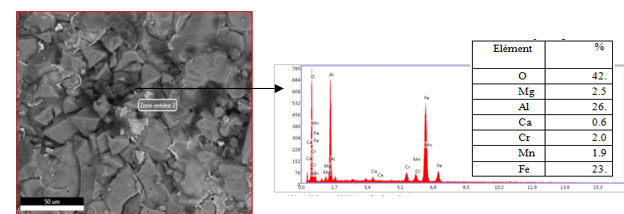
Figure 12: SEM image and chemical composition after EDSLeft side
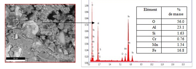
Figure 13: SEM image and chemical composition after EDS Right side
The study of the images of the SEM and EDS of the two faces of the damaged sample shows a similarity from the point of view of chemical composition and structure so we can affirm that the sample rather suffered a brittle fracture at the maximum load of 187.5 kg and not a detachment for the separation, of the dense layer and the refractory wall of the body of the nozzle thus showing a fairly high level of adhesion, which is explained by:
The impregnationzone of the internal walls of the nozzle leaves cavities where steel droplets, containing non-metallic inclusions, freeze, and cause the growth of the initial deposit by accretion phenomenon, we know that these are particles of non-metallic inclusions, remained in suspension which while crossing the nozzle cling to the wall of the tube and cause in time, the reduction of the passage of the metal until the complete reduction of the internal diameter of the nozzle. After nozzle internal fattening, indicates the level of growth of refractory nozzle flow channel clogging, the components of the clogging which react easily with the walls of the nozzle during the passage of the molten steel are oxides.
Roughness Test Result
The roughness test gives us the graphs of Figures 14–16:

Figure 14: Roughness profile of the sample for 45 minutes of holding 750°C

Figure 15: Roughness profile of the sample for 75 minutes of holding 750°C
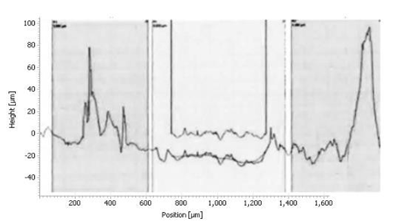
Figure 16: Roughness profile of the sample for 120 minutes of holding 750°C
The histogram in Figure 17 shows the roughness of the sample
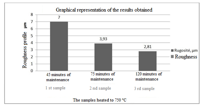
Figure 17: Histogram Indicates the Roughness.
The results of the histograms (Figures 14–16), enabled us to construct the histogram of Figure 17. Indeed, the study of this histogram shows that the roughness decreases with the increase of the time of maintenance of the temperature. The roughness, after 120 minutes of maintenance at a temperature of 750° C., increased from 8.3 μm before heating to 2.81 μm, we can explain this decrease by the crumbling of the spikes during the roughness tests. In the industrial case, the preheating of the nozzles is rather anarchic and unbalanced, which has caused spalling at the level of the internal wall of the nozzle.
Conclusions
Analysis by x-ray fluorescence of the deposit which closes off the casting nozzles revealed that it consists of practically 90% alumina (Al2O3) which comes from the over-consumption of aluminum for the calming of the liquid steel. , the dissolved oxygen content in the steel at the end of refining measured using electrochemical cells is high compared to that of theory (approximately 30 ppm) this can be explained by the fact that the refining cycle is longer long in our case because of the high manganese content in the cast iron, which requires additional blowing in almost 64% of cases.
The deposit adheres very strongly to the lower internal walls of the nozzle. Indeed the interfacial indentation practiced on a deposit sample showed that it was only at more than 187.5 kgf that the sample broke, which represents a fairly high level of adhesion, the examination by eye nu first followed by meb and eds of both sides of the sample showed us that the fracture is of a brittle nature since we have the same chemical composition on both sides of the sample.
Among the factors that increase the adhesion of non-metallic inclusions (Al2O3) on the internal walls of the casting nozzle is the presence of flaking which is due to the overheating of the lower part of the nozzles (more than 1000°C) for a fairly long time (more than 8 hours) in the conditions of steelworks. Indeed, the experiment carried out in our laboratory on three samples heated to 750°C with different holding times has shown that the internal surface condition of the nozzles is smoother, and that there is rather has an improvement in the state of the interior surface as evidenced by the roughness tests Indeed, To minimize the phenomenon of clogging of the nozzles, it is proposed to preheat the nozzles immersed in a furnace, which ensures homogeneous preheating under a controlled atmosphere for an optimal lifespan.
References
- Bai, H., & Thomas, B. G. (2000, March). Effects of clogging, argon injection and casting conditions on flow rate and air aspiration in submerged entry nozzles. In Steelmaking Conference Proceedings (Vol. 83, pp. 183-200).
- Harcsik, B., Tardy, P., & Karoly, G. (2012). Examination of nozzle clogging in continuouscasting. Metallurgical Research & Technology, 109(3), 177-186.
- Mekhenache, F., Snani, L., & Benchikha, T. (2024). Study of the Clogging Phenomenon of Submerged Nozzles in Continuous Casting.
- Smirnov, A. N., Efimova, V. G., Verzilov, A. P., & Maksaev,E. N. (2014). Clogging of submersible nozzles in continuous slab-casting machines. Steel in Translation, 44(11), 833-837.
- Peiyuan ni, Mikael Ersonn, Lage Tord, Ingemar Jonsson, Goran Jonsson School of Metallurgy, Northeastern University, 110819 Shenyang, China and also from the Department of Materials Science and Engineering. Metall 2017
- Smirnov, AN, submersible nozzles for the production of slabs on continuous casting machines, OAO Chermetinformatsiya: Byul. Chern. Metall 2015.
- Spink, J., Carberry, M., Cassar, P., Mizobe, A., Yasuda, T., & Oki, K. (2011). Performance of a new tundish nozzle at operation in a steel plant. Proc. UNITECR'11.
- Takahashi, S., & Yamauchi, T. (2005). Taikabutsu (Journal of Technical Association of Refractories, Japan (TARJ)). Application of anti-clogging material for SEN ports, 57(3), 126.
- Mizobe, A., Yasuda, T., & Tsuduki, T. (2011). New tundish nozzle with the optimum bore profile.

= Refractory material: Krosaki Harima technical report, (159), 29-32. - Mizobe, A., & Ueki, M. (2011). INNER BORE PROFILE OF THE TUNDISH NOZZLE MINIMISING ALUMINAADHESION. Refractories Applications & News, 16(2), 6-13.
- Mizobe, A., & Ueki, M. (2018). Design of nozzle for steel continuous casting system based on flow analysis II- Submerged entry nozzle (SEN)-. Journal of Advanced Mechanical Design, Systems, and Manufacturing, 12(6), JAMDSM0113-JAMDSM0113.
- Mizobe, A., & Ueki, M. (2011). INNER BORE PROFILE OF THE TUNDISH NOZZLE MINIMISING ALUMINAADHESION. Refractories Applications & News, 16(2), 6-13.
- Mekhenache, F., Snani, L., & Benchikha, T. (2024). Study of the Clogging Phenomenon of Submerged Nozzles in Continuous Casting.
- Barati, H., Wu, M., Kharicha, A., & Ludwig, A. (2018). A transient model for nozzle clogging. Powder Technology, 329, 181-198.
- Mekhenache, F., Snani, L., & Benchikha, T. (2024). Study of the Clogging Phenomenon of Submerged Nozzles in Continuous Casting.