

Advances in Bioengineering and Biomedical Science Research(ABBSR)
ISSN: 2640-4133 | DOI: 10.33140/ABBSR

Impact Factor: 1.7

Research Article - (2021) Volume 4, Issue 4
Stress Distribution Along the Implant-Bone Interface: A Pilot Study using Finite Element Analysis to Compare Tilted and Non-Tilted Implants under Different Loads
2Private Dental Clinic, Optim Dental, Peoria, IL, USA
Received Date: Nov 06, 2021 / Accepted Date: Nov 10, 2021 / Published Date: Nov 19, 2021
Copyright: ©Copyright: ©2021 Rui Li. This is an open-access article distributed under the terms of the Creative Commons Attribution License, which permits unrestricted use, distribution, and reproduction in any medium, provided the original author and source are credited.
Citation: Rui Li, Steven Makowka, Sebastiano Andreana, Latifa Bairam, Juhi Hirpara and Jai Kolliboyana (2021) Stress Distribution Along the Implant-Bone Interface: A Pilot Study using Finite Element Analysis to Compare Tilted and Non-Tilted Implants under Different Loads. Adv Bioeng Biomed Sci Res 4(4): 108-113.
Abstract
Introduction: This study used finite element analysis to evaluate stress distribution of implants placed at different angulations under two loadings. Stress was measured at the implant-bone interface.
Methods: Four models of implant and bone were manufactured via three-dimensional optical scanning and point cloud data extraction. They included implants placed: 1) Without tilt 2) tilted at 15o, 3) tilted at 30o, and 4) tilted at 45o. A tissue-level implant was scanned, and a mandible bone model was extracted from cone-beam computed tomography systems. A 3D model of the implants in the mandible were constructed. The finite element analyses were carried out using simulation software. The physical interaction at implant-bone interfaces during loading were considered through bonded surface-to-surface contacts. Static loading (with axial forces of 150N and 300N) were applied to evaluate the implant-bone model.
Results: The amount of stress along the implant-bone interface was greater under 300N loading than 150N loading. The stress along tilted implants were greater than that of non-tilted implants under both 150N and 300N. There was no significant variance among the various angles of implants. The displacements along the tilted implants were larger than those of nontilted implants. The stress distribution along the implant-bone interface increased when the loading increased.
Conclusion: The tilted implants presented greater stress distribution. The in vitro stress distribution analysis using FEA will provide clinical guidance for implant placement.
Keywords
Stress Distribution, Tilted Implant, Finite Element Analysis, Implant-Bone Interface, Loads
Introduction
Over the past few decades, dental implants have risen in popu-larity due to their success in rehabilitating both completely and partially edentulous areas [1]. However, their placement is con-strained by many factors, including anatomy and bone value. The loss of posterior teeth at an early age, for instance, prohibits the placement of implants in related regions due to bone loss, which leads to reduced bone value. In addition, the alveolar nerve canal and the mental nerve loop limit implant placement in the mandibular posterior regions of the mouth. To overcome these issues, bone grafting and short implants have been devel-oped, in addition to inferior alveolar nerve lateral transposition. The use of tilted implants provides another option; it allows for maximum use of existing bone, and placement of posterior fixed restorations with reduced cantilevers. In addition, it circumvents the mandibular nerve [2, 3].
Unlike the mandible, implant stability is restricted in maxilla due to bone resorption, especially in the posterior region. Hence, bone grafting is often indicated in maxillary posterior regions. Another concern for maxillary implant placement is pneuma-tization, in which there is inferior expansion of the maxillary sinus in relation to fixed anatomic landmarks. This condition de¬velops after the extraction of the posterior maxillary teeth [2-6].
To address it, maxillary sinus elevation or bone grafts have been proposed. Pterygomaxillary and zygomatic implants are also op¬tions, but are considered surgically complex [2, 6]. Tilted implants offer an alternative with less morbidity and low¬er financial costs in comparison with other procedures. They can also provide a more postsurgical comfort, as reported in previ¬ous studies [7]. The influence of tilt to the survival and success¬ful rate of dental implants has been studied, revealing that one of key factors of a successful implant is stress distribution at the bone-implant interface [8-11]. However, less is known about the stress distribution of tilted implants.
The finite element method (FEM) is one of the most common methods in stress analysis across a number of scientific fields [12]. Otherwise known as Finite Element Analysis (FEA), this technique has been commonly applied in the quantitative three-dimensional (3D) evaluation of stress distribution along dental implants and surrounding bone [13, 14]. Our research used FEM analysis to evaluate the stress of implants placed at different angles, under a variety of occlusal loads. The null hy-pothesis was that tilted and non-tilted implants would exhibit similar stress distribution along the implant-bone interface, re-gardless of variance in occlusal loads.
Methods
CAD Model and finite element modeling of elements This in vitro study was approved by the University at Buffalo Institutional Review Board (UBIRB).
Four CAD models of implant and bone were manufactured via three-dimensional (3D) optical scanner (Dentium Rainbow Scanner, Dentium) and point cloud data extraction, including implants placed at 1) 0o (used as the control); 2) 15o; 3) 30o; and 4) 45o. A Straumann tissue-level implant (Ø3.3mm RN x 10mm [SLA; Institut Straumann AG, CH-4002 Basel, Switzer¬land]) was scanned with a 3D scanner (Rainbow™, Dentium, USA), and a mandible bone model was extracted from a CBCT DICOM file. The 3D model of the implants in the mandible was constructed via aCAD program (SolidWorks 2010 [Das-sault SystÑmes]). A 3D model of a section of mandible miss¬ing second molar, and its superstructures, was extracted from CBCT. The mandibular bone model was selected as previously described.15 Trabecular bone was modeled as a solid structure encapsulated in cortical bone. A bone block with dimensions of 20mm x 14mm x 35mm, representing the second molar region of the mandible, was modeled. It consisted of a cancellous bone center surrounded by 2mm thick cortical bone. The CAD mod¬el objects had fully bonded contact surfaces (Figure 1). It was assumed that the implant was fully osseointegrated, providing immediate stability after implant placement.
Figure 1: Mandible 3D bone model
FEA Loads
The FEA were carried out using Solidworks® Simulation (Das-sault Systèmes) (Figure 2). The physical interactions at the im-plant-bone interfaces during loading were considered. Static loadings, with an axial force of 150N and 300N, were applied to the implant-bone interface surface. The von Mises stress values were used to measure stress levels and evaluate the stress distri¬bution at the implant-bone interface.

Figure 2. The von Mises stress (MPa) for osseointegration configuration
Results
Figures 3 and 4 show the von Mises stress (MPa) for osseointe-gration configurations under 150N and 300N, respectively. The maximum von Mises stress of the implants under different load¬ings are listed in Table 1. The amount of stress along the angu- lated implants was greater than that on the control group implant under both 150N and 300N loads. There was no significant dif¬ference in stress level among the angled implants. In addition, the von Mises stress under 150N of loading is less than that un¬der 300N of loading, as shown in Table 1.
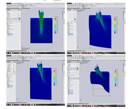
Figure 3: The von Mises stress (MPa) for osseointegration configurations under 15
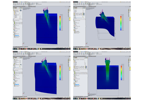
Figure 4: The von Mises stress (MPa) for osseointegration configurations under 300N
Table 1: von Mises Stress
|
Angulation |
von Mises Stress |
|
|
150 N Loading |
300 N Loading |
|
|
00 |
0.4e+008 |
0.7e+008 |
|
150 |
1.1e+008 |
2.2e+008 |
|
300 |
0.7e+008 |
1.5e+008 |
|
450 |
1.6e+008 |
3.1e+008 |
Stiffness Analysis The displacements of implants at different angulations are shown in Table 2. The displacements along the angulated implant were larger than that of the control group implant under both 150N and 300N loads; additionally, there was no significant difference in displacement among differently angled implants (Table 2).
Table 2. Displacement
|
Angulation |
Displacement (mm) |
|
|
150 N Loading |
300 N Loading |
|
|
00 |
0.005 |
0.009 |
|
150 |
0.018 |
0.035 |
|
300 |
0.011 |
0.026 |
|
450 |
0.02 |
0.057 |
Discussion
FEM is the most common tool for analyzing stress distribution of dental restorations under different loading conditions [16, 17]. Three-dimensional FEA virtual modeling, along with appropri-ate stress loads, has been extensively used for the quantitative evaluation of stresses between the implant and its surrounding bone [13, 18]. FEM simulation results have been shown to pro- vide considerable information which cannot be derived from clinical trials, and this data guide innovative designs [19]. It is best to evaluate dental materials using clinical trials; however, time constraints, financial burden, and the need for adequate sample sizes limit such trials [20, 21]. The accurate prediction of dental implant stability and failure mechanisms using FEA provides help in compensating for these [19]. Principal stresses and von Mises stress are both frequently used for interpreting the results of stress analyses in research [21]. The von Mises stress criterion is used to interpret stresses on ductile materials, which are commonly used for implants (e.g., titanium) [21]. As implant failure occurs when von Mises stress values exceed the yield strength of an implant material, we found it meaningful to eval¬uate the von Mises stress distribution along the implant-bone in¬terface of implants placed at various angulations under different loads [22].
The null hypothesis was rejected, as the stress along the tilted implants was found to be greater on the (non-tilted) control group under both 150N and 300N loads. Additionally, the stress under 300N of loading is greater than that under 150N of load¬ing. These results are in accordance with Watanabe et al’s find¬ings [23]. Watanabe et al used a two-dimensional FE model to analyze the influence of load inclination to the stress distribu¬tion between the bone and implant interface. They found that compressive stress at the bone-implant interface increased with implant inclination, regardless of the location and direction of loading [23].
However, other studies yielded different results. Zampelis found that distal tilting of implants splinted by fixed restorations did not increase bone stress in comparison to vertically placed im¬plants [24]. A 2D model for FEA was used in Zampelis’s study, whereas our research used a 3D model). It is important to note that, at the time of Zampelis’ study, 3D models for simulating implants were flat cylinders, which were found to lead to under-estimation of the stress generated at the bone-implant interface. In our study, a 3D model with threads was simulated and used.
Research by Fazi found that a distribution of four implants, with the distal tilted implants at 340 (such as the all-on-four configu¬ration), leads to a favorable reduction of stresses on the bone and implants, and even the restoration framework [14]. Fazi’s study evaluated stresses at the external cortical bone surface, distal to the terminal implant, and in the cancellous bone along the im¬plant body. The current study analyzed the stresses across the entire implant body.
Satoh et al found that using implants tilted mesially at 10-20° did not result in increased stress on the bone [25]. However, the forces applied in Satoh’s study were parallel to the long axis of the tilted implant; in the current study, all forces applied were parallel to the long axis of the non-tilted implant, which is more similar to intraoral occlusal loading. Additionally, the applied loads in our research were 300N and 150N, which correspond to physiologic occlusal loads during chewing and swallowing in patients [26]. It has been well established that implant function and long-term success are mainly dependent on osseointegra-tion with the surrounding bone [22]. The interfacial stress on implants is focused at the interface between the implants and the surrounding bone. This affects the interface biological reactions, including bone resorption and remodeling. Avoiding implant overloading, and ensuring sufficient initial intraosseous stability, are key in promoting a safe biomechanical environment [27].
As a principle, implants placed vertically (without tilt) receive compressive (occlusal) and moderate (lateral) shear forces, most of them directed on the apical third. In the case of tilted implants, these normal forces might lead to uneven stress distribution [6]. Hence, it is necessary to evaluate the stress distribution along tilted implants. This study was limited by the assumption of per-fect contact between the implant and the surrounding bone. Clin¬ically, the implant may only be in partial contact with the bone
Discussion
FEM is the most common tool for analyzing stress distribution of dental restorations under different loading conditions [16, 17]. Three-dimensional FEA virtual modeling, along with appropri-ate stress loads, has been extensively used for the quantitative evaluation of stresses between the implant and its surrounding bone [13, 18]. FEM simulation results have been shown to pro- vide considerable information which cannot be derived from clinical trials, and this data guide innovative designs [19]. It is best to evaluate dental materials using clinical trials; however, time constraints, financial burden, and the need for adequate sample sizes limit such trials [20, 21]. The accurate prediction of dental implant stability and failure mechanisms using FEA provides help in compensating for these [19]. Principal stresses and von Mises stress are both frequently used for interpreting the results of stress analyses in research [21]. The von Mises stress criterion is used to interpret stresses on ductile materials, which are commonly used for implants (e.g., titanium) [21]. As implant failure occurs when von Mises stress values exceed the yield strength of an implant material, we found it meaningful to eval¬uate the von Mises stress distribution along the implant-bone in¬terface of implants placed at various angulations under different loads [22].
The null hypothesis was rejected, as the stress along the tilted implants was found to be greater on the (non-tilted) control group under both 150N and 300N loads. Additionally, the stress under 300N of loading is greater than that under 150N of load¬ing. These results are in accordance with Watanabe et al’s find¬ings [23]. Watanabe et al used a two-dimensional FE model to analyze the influence of load inclination to the stress distribu¬tion between the bone and implant interface. They found that compressive stress at the bone-implant interface increased with implant inclination, regardless of the location and direction of loading [23].
However, other studies yielded different results. Zampelis found that distal tilting of implants splinted by fixed restorations did not increase bone stress in comparison to vertically placed im¬plants [24]. A 2D model for FEA was used in Zampelis’s study, whereas our research used a 3D model). It is important to note that, at the time of Zampelis’ study, 3D models for simulating implants were flat cylinders, which were found to lead to under-estimation of the stress generated at the bone-implant interface. In our study, a 3D model with threads was simulated and used.
Research by Fazi found that a distribution of four implants, with the distal tilted implants at 340 (such as the all-on-four configu¬ration), leads to a favorable reduction of stresses on the bone and implants, and even the restoration framework [14]. Fazi’s study evaluated stresses at the external cortical bone surface, distal to the terminal implant, and in the cancellous bone along the im¬plant body. The current study analyzed the stresses across the entire implant body.
Satoh et al found that using implants tilted mesially at 10-20° did not result in increased stress on the bone [25]. However, the forces applied in Satoh’s study were parallel to the long axis of the tilted implant; in the current study, all forces applied were parallel to the long axis of the non-tilted implant, which is more similar to intraoral occlusal loading. Additionally, the applied loads in our research were 300N and 150N, which correspond to physiologic occlusal loads during chewing and swallowing in patients [26]. It has been well established that implant function and long-term success are mainly dependent on osseointegra-tion with the surrounding bone [22]. The interfacial stress on implants is focused at the interface between the implants and the surrounding bone. This affects the interface biological reactions, including bone resorption and remodeling. Avoiding implant overloading, and ensuring sufficient initial intraosseous stability, are key in promoting a safe biomechanical environment [27].
As a principle, implants placed vertically (without tilt) receive compressive (occlusal) and moderate (lateral) shear forces, most of them directed on the apical third. In the case of tilted implants, these normal forces might lead to uneven stress distribution [6]. Hence, it is necessary to evaluate the stress distribution along tilted implants. This study was limited by the assumption of per-fect contact between the implant and the surrounding bone. Clin¬ically, the implant may only be in partial contact with the bone
Conclusion
Within the limitations of the current research, we concluded that stress distribution along the implant-bone interface increased when the loading increased. Implants which were tilted had greater stress distribution in comparison to non-tilted implants. We recommend further study on this topic to better understand stress distribution and dental implants
References
- Basa S, Varol A, Turker N (2004) Alternative bone expansion technique for immediate placement of implants in the edentulous posterior mandibular ridge: a clinical report. Int J Oral Maxillofac Implants 19: 554-558.
- DeVico G, Bonino M, D Spinelli, R Schiavetti, G Sannino, et al. (2004) Rationale for tilted implants: FEA considerations and clinical reports. Oral Implantol 4: 23-33.
- Krekmanov L, Kahn M, Rangert B, Lindström H (2000) Tilting of posterior mandibular and maxillary implants for improved prosthesis support. Int J Oral Maxillofac Implants 15: 405.
- Zhang C, Wang W, Deepal Haresh Ajmera, Yun Zhang, Yubo Fan, et al. (2006) Simulated bone remodeling around tilted dental implants in the anterior maxilla. Biomech Model Mechanobiol 15: 701-712.
- Graziani F, Donos N, Needleman I, Gabriele M, Tonetti M (2004) Comparison of implant survival following sinus flooraugmentation procedures with implants placed inpristine posterior maxillary bone: a systematic review. Clin Oral Implants Res 15: 677- 682.
- Apaicio C, Perales P, Rangert B (2001) Tilted implants as an alternative to maxillary sinus grafting: a clinical, radiologic, and periotest study. Clin Implant Dentist Relat Res 3: 39-49.
- Harirforoush R, Arzanpour S, Chehroudi B (2014) The effects of implant angulation on the resonance frequency of a dental implant. Med Eng Phys 36: 1024-1032.
- 8. Greenstein G, Cavallaro J (2014) Failed dental implants: diagnosis, removal and survival of reimplantations. J Am Dent Assoc 145: 835.
- DeAngelis F, Papi P, F Mencio, D Rosella, S Di Carlo, et al. (2017) Implant survival and success rates in patients with risk factors: results from a long-term retrospective study with a 10 to 18 years follow-up. Eur Rev Med Pharmacol Sci21: 433-437.
- VanOosterwyck H, Duyck J, J Vander Sloten, G Van der Perre, M De Cooman, et al. (1998) The influence of bone mechanical properties and implant fixation upon bone loading around oral implants. Clin Oral Implants Res 9: 407-412.
- Geng J, Tan BC, Liu G (2001) Application of finite element analysis in implant dentistry: A review of the literature. J Prosthet Dent 85: 585-598.
- SalehSaber F, Ghasemi S, Koodaryan R, Babaloo A, Abol-fazli N (2015) The comparison of stress distribution with different implant numbers and inclination angles In All-on-four and conventional methods in maxilla: A Finite Element Analysis. J Dent Res Dent Clin Dent Prospects 9: 246-253.
- DeTolla DH, Andreana S, Patra A, Buhite R, Comella B (2000) Role of the finite element model in dental implants. J Oral Implantol 26: 77-81.
- Fazi G, Tellini S, Vang D, Branchi R (2011) Three-Dimensional Finite Element Analysis of Different Implant Configurations for a Mandibular Fixed Prosthesis. Int J Oral Maxillofac Implants 26: 752-759.
- Lekholm U, Zarb GA (1985) Patient selection and preparation. Tissue integrated prostheses: osseointegration in clinical dentistry. Quintessence Publishing Company, Chi-cago1985: 199-209.
- VanStaden RC, Guan H, Loo YC (2006) Application of the finite element method in dental implant research. Comput Methods Biomech Biomed Engin 9: 257-270.
- Maminskas J, Puisys A, Kuoppala R, Raustia A, Juodzbalys G (2016) The prosthetic influence and biomechanics on peri-implant strain: a systematic literature review of finite element studies. J Oral Maxillofa Res 7: 4.
- Esposito M, Worthington H, Thomsen P (2013) Interventions for replacing missing teeth: different times for loading dental implants. Cochrane Database Syst Rev 3: CD003878.
- Tang CB, Liu SY, Guo Xing Zhou, Jin Hua Yu, Guang Dong Zhang, et al. (2002) Nonlinear finite element analysis of three implant–abutment interface designs. Int J Oral Sci 4: 101-108.
- Nasappan T, Ariga P (2014) Comparison of Stresses Around Dental Implants Placed in Normal and Fibula Reconstructed Mandibular Models using Finite Element Analysis. J Ciln Diagn Res 8: 45-50.
- Eskitascioglu G, Usumez A, Sevimay M, Soykan E, Un-sal E (2004) The influence of occlusal loading location on stressestransferred to implant- supported prostheses and supporting bone: a three-dimensional finite element study.J Prosthet Dent 91: 144-50.
- Ebrahimi F (2012) Finite Element Analysis: New Trends and Developments. Intechopen 2012: 1-414.
- Watanabe F, Hata Y, Komatsu S, Ramos TC, Fukuda H (2003) Finite element analysis of the influence of implant inclination, loading position, and load direction on stress distribution. Odontology 91: 31-36.
- Zampelis A, Rangert B, Heijl L (2007) Tilting of splinted implants for improved prosthodontic support: a two-dimensional finite element analysis. J Prosthet Dent 97: 35-43.
- Sato Y, Wadamoto M, Tsuga K, Teixeia ER (1999) The ef-fectiveness of element downsizing on a three-dimensional finite element model of bone trabeculae in implant biomechanics, J Oral Rehabil 26: 288-291
- Gibbs C, Mahan P, Lundeen H (1982) Occlusal forces during chewing and shallowing as measured by sound transmission. J Prosthet Dent 46: 443-49.
- Pessoa RS, Muraru L, Júnior EM, Vaz LG, Sloten JV, et al. (2010) Influence of implant connection type on the biomechanical environment of immediately placed implants - CT-based nonlinear, three-dimensional finite element analysis. Clin Implant Dent Relat Res 12: 219-234.