
Advances in Machine Learning & Artificial Intelligence(AMLAI)
ISSN: 2769-545X | DOI: 10.33140/AMLAI
Impact Factor: 1.755

Research Article - (2025) Volume 6, Issue 4
Resistance of Resonance Phenomena and its Application
Received Date: Oct 09, 2025 / Accepted Date: Nov 05, 2025 / Published Date: Dec 17, 2025
Copyright: ©2025 Kazuyuki Ouchi. This is an open-access article distributed under the terms of the Creative Commons Attribution License, which permits unrestricted use, distribution, and reproduction in any medium, provided the original author and source are credited.
Citation: Ouchi, K. (2025). Resistance of Resonance Phenomena and its Application. Adv Mach Lear Art Inte, 6(4), 01-04.
Abstract
By applying a voltage to the piezoelectric material, the resonance phenomenon of the piezoelectric set between the electrodes had been utilized. In addition, in the use of capacitors as electrical circuits, accidents caused by abnormal currents from the resonance phenomena between electrodes occurred. For these resonance phenomena, the impedance between the electrodes was calculated by using a wave equivalent circuit. It was found that resonance phenomena occur in both elastic and electromagnetic waves, and resonance phenomena occur in response to the mode of COS distribution between electrodes. For the purpose of using as a magnetic field generator for MRI (Magnetic Resonator Imaging) of medical observation equipment, on the condition of in a moment and at a point, the strength of the magnetic field from resonance phenomena was compared with the strength of the magnetic field required for MRI. It was found that the magnetic field strength required for MRI was satisfied by the size of the electrode and the frequency
Keywords
Resonance phenomena, Interelectrode characteristics, Wave equivalent circuits, Mason's equivalent circuits, MRI, Magnetic field generation
Introduction
By installing electrodes at both ends of the piezoelectric material and applying voltage, the acoustic wave device (BAW device) was designed and manufactured as an efficient wave device for the oscillator by obtaining low resistance by utilizing the resonance characteristics between the electrodes. In addition, the electrodes were arranged in the direction of wave travel and the polarity of the electrodes was alternately applied to +, − to generate high- frequency elastic waves, which were used in the development and manufacturing of device technologies such as resonators and filters at high frequencies [1].
In addition, electrode configurations similar to elastic waves have been proposed for electromagnetic waves [2]. These structures are composed using the characteristics between the electrodes. By using the impedance between the electrodes, the characteristics between the electrodes are clearly used.
And, it was known that resonance occurs at half wavelength of alternating voltage. Since resonance is related to frequency, a wave equivalent circuit was applied between the electrodes. First, the impedance between the electrodes was calculated by expressing the wave equivalent circuit. We adapted Mason's equivalent circuit with clear electrical terminals [3]. Then, the interelectrode impedance was obtained and the characteristics between the electrodes were clarified.
We obtained resistance at the resonance point and proposed its application. We examined whether it can be adapted as a magnetic field for MRI equipment [4]. What is required for MRI equipment is a strong static magnetic field. Although it is not yet possible to achieve a static magnetic field, we examined whether the interelectrode resonance phenomenon can be used as the strength of the magnetic field. For a moment, I calculated whether the intensity in one place was satisfactory to the magnetic field required by the MRI machine. We compared the strength of the magnetic field at a moment and at a point rather than a static magnetic field.
Resonance Phenomena
A schematic diagram of the electrode and the AC power supply is shown in Fig. 1. When an AC voltage is applied between the electrodes, a resonance phenomenon occurs.
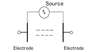
Figure 1: Schematic diagram of electrodes and AC power supply
The space between electrodes is represented by a wave equivalent circuit. When the inner resistance of electric source is zero and the output resistance of wave circuit equivalent is zero, input impedance for the input terminal is calculated. Fig2 shows equivalent circuits with conditions for calculating Mason’s equivalent circuit.
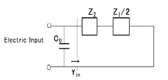
Figure 2: Equivalent circuits with conditions for calculation
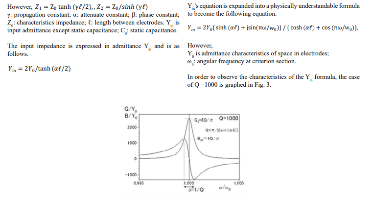
Figure 3: Characteristics of input admittance when Q = 1000
The vertical axis is the conductance G of Yin/Y0 (graph where the peak vertex is w/w0 = 1) and susceptance B of Yin/Y0 (graph when w/w0 = 1, B/Y0 = 0 and it waves larger in the center of w/w0 = 1), and the horizontal axis is w/w0.
The graph of G is a conductance that rises sharply and is the highest value at the resonance point. The values of each point of G/Y0 and B/Y0 are written in Fig. 3, and each value at extremely large and small is obtained by taking the differential coefficient at the from the formula G/Y0 and B/Y0.
Resonant Characteristics
In the resonance graph in Fig. 3, w/w0 = 1 is the resonance point.
The maximum conductance G0 at the resonance point is, from the Yin equation,
And susceptance B/Y0 = 0.
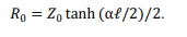
This resistor formula does not include the electrode area S. Considering the electrode area, R become
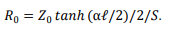
So, at resonant point impedance is resistance only. Fig.4 shows the equivalent circuit at resonant point.
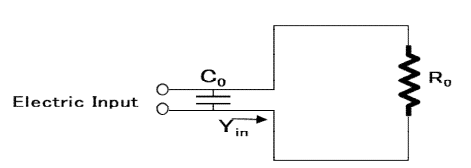
Figure 4: Equivalent circuit at resonant point
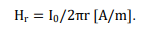
When the resonant current I0[A] flows between the electrodes, the magnetic field Hr according to Ampere's law at r[m] far away is
Calculate magnetic field from resonant resistance
As a premise, calculate how strong the magnetic field is in one place at a moment, and it does not matter whether the strength of the magnetic field can be sustained in time or space. Calculate only the strength of the magnetic field.
Arrange in order, resonant resistance Ro , resonant current Io magnetic field Hr.
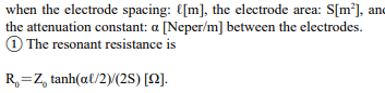
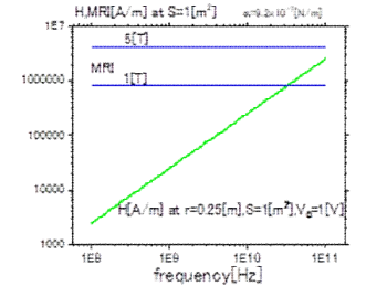
Figure 5: Compare the magnetic field necessary for MIR with magnetic field induced from resonant current
From Fig.5, at about 30[GHz], magnetic field calculated from resonant phenomena calculated reaches to magnetic field necessary for MRI. The result here is in the case of one point at a moment
Summary
The resonance phenomenon between electrodes was clarified using a wave equivalent circuit. The resistance at the resonance point was determined by obtaining the impedance between the electrodes. The magnetic field was calculated from Ampere's law using the obtained resistance of the resonance point. Only the magnetic field required for the MRI machine is satisfied by the conditions, albeit in one place for a moment.
References
- Kazuhiko, Y. (2004). Elastic-dynamic Wave Device Technology, 150th Committee Editor's Representative.
- Ouchi, K. (2022). Elastic wave and electromagnetic waveguide analysis--Configuration technology about ΔV/V waveguide and intrinsic vibration mode. IEICE Technical Report; IEICE Tech. Rep., 122(20), 14-17.
- Ouchi, K. (2022). Wave resonant characteristics between parallel plate electrodes. IEIC Conference Archives.
- Ouchi, K. (2025). Magnetic field generation for MRI using resonance phenomenon--Magnetic fields required for MRI and magnetic fields us ing resonance phenomena. IEICE Technical Report; IEICE Tech. Rep., 125(176), 17-19.