

Advances in Machine Learning & Artificial Intelligence(AMLAI)
ISSN: 2769-545X | DOI: 10.33140/AMLAI
Impact Factor: 1.755

Research Article - (2026) Volume 7, Issue 4
Predictive Maintenance for Industrial Machines
Received Date: Sep 29, 2026 / Accepted Date: Nov 09, 2026 / Published Date: Nov 16, 2026
Copyright: ©2026 Antimo Angelino. This is an open-access article distributed under the terms of the Creative Commons Attribution License, which permits unrestricted use, distribution, and reproduction in any medium, provided the original author and source are credited.
Citation: Angelino, A. (2026). Predictive Maintenance for Industrial Machines. Adv Mach Lear Art Inte, 7(4), 01-06.
Abstract
Maintenance Engineering is the corporate function that manage all maintenance activities for industrial machinery and plants, aiming to maximize their availability and efficiency while reducing operational costs. In this context, predictive maintenance emerges as the methodology capable of reducing both costs and downtime, aiming to predict failures before they occur. This also enables a transition from a reactive intervention logic to a proactive one. This work illustrates a real-world application within the defence industry sector, outlining the key phases of the project and the main features of the predictive system.
Keywords
Predictive Maintenance, Industrial Machine, PLC, OPC-UA, AutoencoderIntroduction
Why Predictive Maintenance
Over the last two decades, the industrial sector has undergone a deep transformation driven by the introduction of increasingly advanced automation systems, the integration of digital technologies, and the widespread deployment of IIoT1 sensors. Furthermore, the high complexity of industrial machines, combined with growing market competitiveness, has made it necessary to adopt maintenance strategies capable of ensuring ever-higher levels of availability and reliability while simultaneously lowering operational costs. Maintenance has therefore become an integral part of corporate strategy, where the objective is no longer merely repairing failures but guaranteeing the maximum availability of machinery and plants while optimizing management costs. Consequently, the concept of maintenance engineering was born. In this framework, predictive maintenance represents one of the most effective methodology today for increasing the productivity of industrial facilities.
Unlike corrective maintenance (which intervenes after a failure occurs) and preventive maintenance (which schedules interventions at predetermined time intervals), predictive maintenance bases its decisions on the actual condition of the machine (detected through continuous monitoring systems) and intervenes before the failure occurs. This is clearly illustrated by Figure 1, which shows the classic P-F curve, where it can be observed that predictive maintenance detects a potential failure long time before it manifests as a physical machine breakdown. The P-F curve (where P stands for Potential Failure and F for Functional Failure) charts the life cycle of a degradation process. The point P identifies the exact moment when the earliest symptoms of a problem become detectable through behavioral anomalies. The point F identifies the moment when the machine can no longer perform its intended design function. The approach has thus shifted from repairing faults as they happen or performing scheduled actions at fixed intervals, to forecasting the onset of failures with sufficient notice to plan maintenance activities at the optimal moment. This also allows organizations to move beyond a reactive logic and adopt a predictive one.

Figure 1: P-F Curve
Theoretical studies supported by consolidated industrial experience demonstrate that the implementation of predictive maintenance policies yields efficiency gains and operational cost reductions in the range of:
• Failure reduction: approximately 90% reduction in corrective maintenance
• Preventive optimization: around 30% reduction in preventive maintenance
• Spare parts management: approximately 50% reduction through spare parts optimization
How to Build a Predictive Maintenance System
The general architecture of a predictive maintenance system is illustrated in Figure 2 and essentially consists of a data acquisition system, a data analysis and prediction model, and a reporting alarm system.

Figure 2: Predictive Maintenance System
The fundamental elements required to build a predictive maintenance system are:
• Machine knowledge
• Selection of the data acquisition system
• Design of the data analysis and prediction model
• Connectivity availability
• Evaluation of cybersecurity constraints
These factors influence not only design choices but the entire project execution. The technical knowledge of the machine dictates three distinct strategies:
• Cloud Manufacturer Model: machine manufacturer produces the predictive model and uses it with data collected and sent (via cloud) by the machine users. This is normally the case in which “specific user conditions” don’t affect the prediction and the machine manufacturer doesn’t share knowledge.
• On-premise Manufacturer Model: machine manufacturer produces the predictive model and sells it to the machine users that use it with data collected within machine user premises. This is the case in which “specific user conditions” affect the prediction model.
• User-Developed Modelling: machine users develop the prediction models using their engineering knowledge and maintenance experience. Adv Mach Lear Art Inte, 2026 Volume 7 | Issue 4 | 2 Meanwhile, the choice of the acquisition system is directly tied to the specific typology of the data to be captured:
• External IIoT sensors connected via MQTT2 to acquire environmental signals (normally: temperature, vibration and noise).
• Direct access to PLC3 via OPC-UA4 to acquire machine variables status (normally: axis velocity, acceleration, current consumption).
The Project Developed at MBDA Italia S.p.A.
The following section describes the predictive maintenance project applied to a combined industrial turn-mill lathe machine, developed and currently operating at the MBDA Italia S.p.A. production plant in Fusaro (NA).
As this was a legacy machine, no manufacturer-developed predictive model was available. Consequently, the engineering team proceeded to build the model independently based on technical knowledge and historical maintenance experience. The engineering design can be summarized in the following steps:
1. Identify and select signals to acquire (representative of machine working status)
2. Acquire standard behaviour for selected signals
3. Train predictive model using standard behaviour of selected signals
4. Monitor in real time the selected signals and compare with standard one, detecting anomaly behaviour
5. Following a signal anomaly detection, use machine knowledge and maintenance experience and physical machine inspection to correlate signal anomaly behaviour with upcoming failures
6. In case of an anomaly detection, store the signals with anomaly behaviour for further analysis
7. Build a knowledge base correlating signals anomaly behaviour with machine failures
The first phase involved identifying the specific signals to acquire and monitor, whose anomalous behaviour was linked to machine malfunctions. Since deep knowledge of the machine was limited, it was difficult to determine optimal locations to place external IIoT sensors for capturing vibration, temperature, and noise in a way that accurately indicated failures. Therefore, the team elected to harvest signals directly from the PLC regarding the main variables representing machine operations. Among more than 1,000 variables available on the machine's Siemens S75 PLC, just over 50 were selected, as shown in Figure 3.

Figure 3: Signals Selected from PLC
Data acquisition was executed via an Ethernet link utilizing the OPC-UA protocol, given that machine connectivity is secured through an industrial network compliant with the ISA-95 standard, exchanging data according to the Purdue Model6. Thus, a standard machining operation lasted several hours, data acquisition was segmented into time windows tied to specific machine instructions (thereby eliminating the distortion effects of override, potentially introduced by operators). Furthermore, because the signals were highly discontinuous, and to ensure a mathematically sound comparison between the real-time signal and the nominal baseline, six representative parameters were extracted from the signals within each acquisition window: maximum value, minimum value, mean, variance, integral, and derivative. The core of the predictive architecture is represented by an autoencoder (Figure 4), a specific artificial neural network model whose transfer function is detailed in the following formula.

For this particular industrial application, the autoencoder was implemented using LSTM (Long Short-Term Memory) artificial neural networks. Below there is the Python code for a generic 3-layer autoencoder:

Figure 4: Autoencoder Architecture
The autoencoder was trained using nominal signals acquired during a standard machining production cycle. During the inference phase it is inputted with real-time signals acquired from the machine, outputting rebuilt versions of its inputs. Consequently, if the input signal matches the nominal baseline used during training, the reconstructed output will closely resemble the input. Conversely, if the real-time input signal deviates substantially from the standard baseline, the reconstructed output will be entirely different from the input. Downstream of the autoencoder, a system based on fuzzy logic with three distinct classes and discrimination thresholds was implemented. This system is fed by the module difference between the real-time signal acquired from the machine (autoencoder input) and the reconstructed signal (autoencoder output).
For immediate visual impact, the classes were mapped to classic traffic-light colours:
•  Green: correctly working – between 0 and 25 %
•  Yellow: warning - between 25 and 50 %
•  Red: upcoming failure - major 50 %
Figures 5 and 6 illustrate some of the verification tests performed on the system prior to deployment into production. In these images, the following signals are graphically aligned: the nominal signal used to train the autoencoder, the real-time input to the autoencoder, the reconstructed output signal, the absolute difference between input and output, and the final class computed by the fuzzy logic system.

Figure 5: Autoencoder Test with Dummy Signal
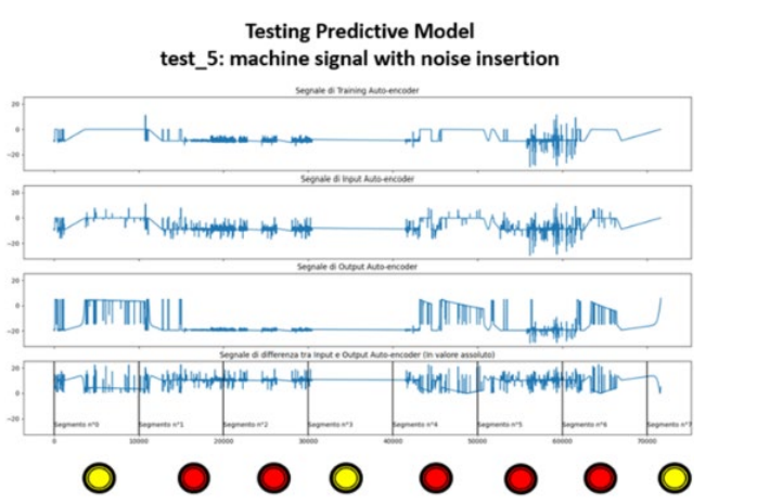
Figure 6: Autoencoder Test with Real Signal
Training data was collected over approximately two weeks during production runs on various components. The testing phase lasted about six months, during which the detection thresholds of the fuzzy logic classes were refined and calibrated before the system was officially launched into production. The user interface displayed by the predictive maintenance system is shown in Figure 7.

Figure 7: Predictive Model Dashboard
Conclusions and Future Developments
Following an initial tuning phase, the predictive system is successfully operating for more than three years, proving capable of forecasting the majority of recurring faults and largely confirming the expected operational benefits. The engineering expertise gained during the project development in the Fusaro plant was shared across other manufacturing sites within the broader MBDA Group7, leading to the creation of a dedicated, international working group. Furthermore, during these years, the introduction of highly demanding machining operations caused a highly increase in the computational load (particularly the LSTM autoencoder), necessitating a hardware platform upgrade. So, to address long-term scalability, a research pilot has been launched focusing on a hybrid classical-quantum autoencoder model. In the near future, utilizing industrial-grade quantum computers, this framework aims to effortlessly manage massive computational workloads [1-11].
References
- Bourlard, H., & Kamp, Y. (1988). Auto-association by multilayer perceptrons and singular value decomposition. Biological cybernetics, 59(4), 291-294.
- Hochreiter, S., & Schmidhuber, J. (1997). Long short-term memory. Neural computation, 9(8), 1735-1780.
- Kosko, B. (1992). Neural networks and fuzzy systems: a dynamical approach to machine intelligence (p. 449). Englewood Cliffs, NJ: Prentice Hall.
- Sakhnenko, A., O’Meara, C., Ghosh, K. J., Mendl, C. B., Cortiana, G., & Bernabé-Moreno, J. (2022). Hybrid classical-quantum autoencoder for anomaly detection. Quantum Machine Intelligence, 4(2), 27.
- Angelino. A. (2024). Data & AI for Industrial Application.Adv Mach Lear Art Inte, 5(4), 01-07.
- Górny, A., & Jasiulewicz-Kaczmarek, M. (2026). The Machinery Regulation (EU) 2023/1230 in the Development of Operational Safety Assurance. In Design, Simulation, Manufacturing: The Innovation Exchange (pp. 371-386). Cham: Springer Nature Switzerland.
- ISA-IEC 62443-x (x=1, 4). Security for industrial automation and control systems.
- Chen, D. (2005). Enterprise-control system integration—an international standard. International journal of production research, 43(20), 4335-4357.
- IEC 62541-x (x =1, 7). OPC Unified Architecture
- Moubray, J. (2001). Reliability-centered maintenance. Industrial Press Inc.
- Bolton, W. (2003). Mechatronics: electronic control systems in mechanical and electrical engineering. Pearson Education.
Foot notes
1Industrial Internet of Things
2 Message Queuing Telemetry Transport is a communication protocol described into ISO/IEC 20922, used for IoT sensors
3 Programmable Logic Controller, a specialized industrial computer designed to manage and automate manufacturing processes within factories and plants
4 Open Platform Communications Unified Architecture is a communication protocol described into IEC 62541, used for industrial applications
5 https://www.siemens.com/en-us/products/simatic/
6 Formally known as PERA (Purdue Enterprise Reference Architecture), is the global reference model describing hierarchical structure and segmentation of industrial networks. Developed in the early 1990s by Theodore J. Williams and the Purdue University consortium