




Research Article - (2026) Volume 4, Issue 6
Physiopathological Effects of Electric Current on the Human Body and the Protection Against Electric Shocks
 , Maria Almeida 3 , Catarina Silva 3 and Carolina Costa 3
 2Center for Innovation in Engineering and Industrial Technology (CIETI), Polytechnic Institute of Por, Portugal
3Infante D. Henrique Family Health Unit. 3510-046 Viseu, Portugal
Received Date: May 12, 2026 / Accepted Date: Jun 09, 2026 / Published Date: Jun 15, 2026
Copyright: ©2026 Jose Carvalho, et al. This is an open-access article distributed under the terms of the Creative Commons Attribution License, which permits unrestricted use, distribution, and reproduction in any medium, provided the original author and source are credited.
Citation: Carvalho, J., Almeida, M., Silva, C., Costa, C. (2026). Physiopathological Effects of Electric Current on the Human Body and the Protection Against Electric Shocks. Eng OA, 4(6), 01-16.
Abstract
In electrical installations and equipment, electric current preferentially flows through metallic circuits that offer it less opposition, that is, less electrical resistance. In the human body, electric current also seeks to flow through paths with less electrical resistance, and may be diverted inside the body, damaging surrounding organs and tissues. Its path and the magnitude of the current influence the type of injuries associated with electrical accidents, usually burns, which can be internal and external. In all electrical installations, there is a need and obligation to implement effective protection systems, with the aim of operating them under safe conditions. In Low Voltage Electrical Installations (LVEI), the protection measures that must be considered are overcurrent protection, overvoltage protection, but fundamentally the protection of people from the risk of electrocution, avoiding pathophysiological effects that can be irreversible.
Keywords
Electric Shock, Electrocution, Pathophysiological Effects of Electric Current, Injuries Due to Electric Current, Protection of People, Grounding Systems
Abbreviations
The following abbreviations are used in this manuscript:
LVEI Low Voltage Electrical Installations
CNS Central Nervous System
ELT Grounding Scheme Methodologies
CPI Permanent Isolation Controllers
UL Electrical Voltage Limit
Uc Contact voltage
Introduction: Electrical Accidents
The consequences of electrical accidents depend on several factors, including a) potential difference or elec-trical voltage (Volts), b) current intensity (Amperes), c) electrical resistance (Ohms), d) type of electrical current (direct or alternating), e) current path, f) ambient humidity and g) duration of current flow [1,2,4]. According to the IEC 60479-1 standard, the pathophysiological effects of alternating current between 15 and 100 Hz are shown in Figure 1 [3].
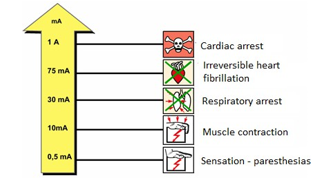
Figure 1: Critical Current Values and their Respective Pathophysiological Effects
Considering the duration of the current through the human body, the same IEC 60479-1 standard defines time/current zones and relates them to the pathophysiological effects of alternating current on the human body, when the current passes between the left hand and the foot, as shown in Figure 2[3].

Figure 2: Time/Current Zones and Respective Pathophysiological Effects on the Human Body
In zone AC-1 there is no perception of current. In zone AC-2, perception of the passage of current through the human body is already evident. Zone AC-3 is already characterized by the manifestation of reversible path-ophysiological effects; such as muscle contraction. In zone AC-4, irreversible pathophysiological effects may already manifest. Curve C1 is very important, as it delimits the zone of reversible pathophysiological effects from irreversible ones. For time/current values to the right of this curve, ventricular fibrillation may already manifest. This probability is 5% to the right of curve C2, but increases to 50% for time/current values to the right of curve C3.
As for the type of current, direct or alternating, it is observed that the perception of the human body is par-ticularly sensitive to alternating current at a frequency of 50 Hz, which is the frequency value of the electrical energy that is produced and distributed for use by European electrical networks. This relationship is shown in Figure 3.

Figure 3: The Highest Sensitivity for the Human Body is at Frequency Values of 50 Hz.
Physiopathological Effects of Electric Current on the Human Body
The effects of electric current on the human body, fundamentally internal or external burns, can be classified, according to the pathophysiological mechanism, into three types: a) electrical injury caused by the current itself, b) arc injury, when the current is transmitted from the source to an object, and c) flame injury. Traumatic injuries, eardrum rupture, and contusions of internal organs can also occur [4]. Normally, electric current flows through a specific path from the entry point to the exit point, forming a circuit characterized by a potential difference between the entry and exit points. The most frequent entry points are the hands and head, and the exit points are the hands, feet, and legs [2]. In the case of alternating current, these concepts are not as relevant. However, there is an increased health risk when dealing with alternating current, particularly in the 50-60 Hz range (Figure 3), as this is associated with tetanic muscle spasms, and the cardiovascular and respiratory systems appear to be the most sensitive to this type of current [2].
Electrical accidents, according to their severity, are divided into low and high risk and are distinguished ac-cording to the following characteristics presented in Table 1:
Table 1: Comparison between High and Low Risk Electrical Accidents [1].
|
Causes |
Low risk |
High risk |
|
Electrical voltage |
<1000 volts |
>1000 volts |
|
Current type |
Direct |
Alternating |
|
Exhibition duration |
Short |
Prolonged |
|
State of consciousness |
On watch |
(Initially) Unconscious |
|
ECG (electrocardiogram) |
Normal/previous pathology |
New pathology |
|
Skin changes |
Minor/none |
Deep/extensive |
|
Laboratory abnormalities |
Irrelevant |
Elevated Creatinaquinase (CK), creatinine, and potassium levels. |
|
ICD/IV device (defibrillation device) |
No |
Present |
Cutaneous-Muscular and Osteoarticular Systems
The skin, the most common entry point in electrical accidents, is characterized by high resistance to the passage of current. This resistance, however, is reduced by moisture. Muscle spasms induced by electric current and tetany can result in the inability to release the source of the electric current, known as the “non-let-go phenomenon” [1]. Because bone has high electrical resistance, the current is more easily converted into thermal energy, resulting in burns and necrosis [1,4]. Dry skin and the resistance offered by bone to electric shock generate high temperature gradients, one of the factors that contribute to deep muscle necrosis [4,5]. Other factors include diffuse vascular lesions and the development of compartment syndrome.
In cases of current-associated injuries due to high voltage, accident victims have a higher risk of spinal fracture due to tetany. Tetany can also be caused by alternating current [4].
Tissue necrosis, arterial lesions, and rhabdomyolysis can lead to amputation due to functional loss, com-partment syndrome, and renal failure [6].
Cardiovascular System
The main cardiac complications are arrhythmias [4,7]. These can develop independently of the magnitude of the voltage. Other relevant cardiovascular injuries also include coronary artery spasm and myocardial tissue damage [4,7]. The most frequent arrhythmias in cases of electrical accidents vary from sinus tachycardia and ventricular extrasystoles to ventricular fibrillation and asystole or atrial fibrillation [4,7,8]. However, there are cases of sinus bradycardia, bundle branch blocks or atrioventricular blocks after electrical shocks. Most of these events occur immediately after the electrical shock, but there are reports of late-onset arrhythmias [7].
The mechanism of action is not fully understood, but myocardial tissue biopsies point to arrhythmogenic foci associated with irregular myocardial fibrosis, increased number of sodium and potassium pumps and changes in membrane potential. Consequently, arrhythmias can be triggered by areas of repolarization heterogeneity, with abnormal increases in automaticity or afterdepolarization, and can trigger activity hours after injury. Areas of necrosis or scarring can promote the development of reentrant arrhythmias [7]. The electrical current also appears to exert an effect on the sinus and atrioventricular nodes, and it has been hypothesized that their ion channels are more easily affected and that ischemia in the area supplied by the right coronary artery makes these areas more vulnerable to the current [7].
Interestingly, lesions in the conduction pathway secondary to electrical shock are the basis for the development of ablation techniques. In 1979, atrioventricular block resulting from an external electrical shock that spread through an electrode positioned in the bundle of His was described [7]. The vascular bed is an excellent conductor due to its highwater content. Electrical accidents most frequently affect small blood vessels. Normally, large-caliber arteries are not acutely affected because their rapid flow allows the heat produced by the electric current to dissipate. However, these vessels are susceptible to necrosis of the medial layer, which can result in aneurysm and subsequent rupture.
Other cardiovascular consequences associated with electrical accidents include: a) acute myocardial infarction (due to coronary spasm or thrombosis), b) myocardial contusion from cardiopulmonary resuscitation, c) injuries mediated by extensive catecholamine release, d) reduced coronary blood flow secondary to severe generalized hypotension, e) Brugada pattern, f) hemorrhagic pericarditis, g) transient arterial hypertension, and h) transient autonomic dysfunction. Diagnosis of these alterations can be difficult due to the absence of typical complaints, such as chest pain, and specific ECG changes [7].
Although cardiac function usually returns to normal after an electric shock, some cardiac abnormalities may persist over time. However, heart failure with reduced ejection fraction has rarely been reported [7]. The literature refers to major and minor criteria for detecting the passage of electrical current in cardiac tissue as referred to below [9].
The major criteria may be:
• Macroscopic: hemorrhagic areas on the cardiac surface;
• Microscopic: myocardial fragmentation with myocytes alternating between hypercontraction and hyperdistention, rupture of myocardial fibers and necrosis of the contraction band [9].
Minor criteria include the following microscopic criteria: focal degeneration of smooth muscle fibres, ex-pression of the myocyte nucleus, segmentation of intercalated discs, changes in epicardial cardiac nerves with central endoneurais fissures of nerve fibres and perineural detachment, edema of nerve fibres and subperineural space [9]. In addition, studies show that, after a burn, individuals present a state of hypercoagulability. This state of hypercoagulability does not appear to be related to the type of burn or the total area of the body surface affected. It is also associated with increased platelet lysis and reduced platelet function [10].
Nervous System
Electric shock can affect both the Central Nervous System (CNS) and the Peripheral Nervous System. Loss of consciousness, for example, is very common [2]. Neuropathies are common complications resulting from electrical accidents [6]. According to a 2021 systematic review, several peripheral neuropathies have been reported, including Mononeuropathies, polyradiculopathies or peripheral polyneuropathies, and cranial nerve lesions [2].
Mononeuropathies are the most frequent, occurring mainly in accidents with electrical currents originating from lower voltage, and can occur due to direct injury or compression secondary to edema [2]. Some researchers support the hypothesis that electrical burns, to the same extent as thermal burns, can cause mononeuropathy of the median nerve due to increased temperature within the carpal tunnel. This nerve is particularly vulnerable to the action of electric current due to its low resistance and surrounding vascularization. Consequently, the typical symptoms of compressive peripheral neuropathy appear, on average, 2 months after hospital discharge. The onset of intraneural fibrosis leads to irreversible fascicular atrophy, even after possible surgical release [11]. Multiple bilateral Mononeuropathies can also occur, most frequently in the context of third- or fourth-degree burns. Polyradiculopathy is associated with the existence of multiple entry points. Cranial nerve involvement may increase the risk of developing tinnitus and vertigo throughout life [11].
CNS lesions are highly variable. Myelopathy usually has an immediate onset and is more common in electrical injuries due to higher voltages. Traumatic brain injuries can also occur, presenting with various symptoms, including headache, nausea, behavioural and/or memory changes, paralysis, seizures, aphasia, and coma. The basal ganglia appear to be more sensitive to this type of injury [2].
Ischemic CNS lesions are less frequent than haemorrhagic lesions, and the main mechanism is vasospasm. Cases of transient or permanent cerebellar syndromes have also been reported. Other CNS consequences include hydrocephalus, cerebral edema, cerebral venous thrombosis, and movement disorders. Epilepsy can be a late consequence of electrical trauma, as can myoclonus. Current evidence also seems to suggest a higher prevalence of amyotrophic lateral sclerosis in electricity-related professions, and meta-analyses consider electrocution as an important risk factor [2].
There are also some nonspecific clinical findings after an electrical accident, such as abnormal pupillary reactions, such as fixed and dilated pupils or anisocoric due to Horner’s syndrome, a consequence of reversible autonomic dysfunction (3,6). Damage to the autonomic nervous system can also result in complex regional pain syndromes, autonomic cardiovascular complications, and Charcot’s paralysis [2].
Respiratory System
Following an electrical accident, respiratory arrest may occur immediately due to inhibition of the respiratory center or prolonged paralysis/tetanic contraction of the diaphragm or other respiratory muscles. Direct damage to the lung parenchyma is rare, but thermal burns to the respiratory tract may occur due to inhalation of toxic gases or hot debris [7].
Gastrointestinal System
Visceral injuries resulting from electrical burns are rare but potentially serious [12]. The intestine is the most frequently affected organ, and injuries to the oesophagus, stomach, liver, gallbladder, pancreas, kidneys, and lungs are occasionally reported. Liver dysfunction is common in patients with severe thermal burns, while liver lacerations are rarely described [12]. In one case report, a liver laceration was observed after an electrical accident: a 47-year-old bricklayer accidentally touched a high-voltage alternating current wire (14 kV). This resulted in burns to the right abdomen, hand, and thighs, without associated trauma. The burns were “treated” by the patient himself. Due to worsening pain, he went to the emergency room, where the following were observed: third-degree burns on the right hand, second-degree burns on the right abdomen, and a small burn on the right thigh. The abdomen was soft but uncomfortable on deep palpation. Abdominal ultrasound revealed the presence of fluid in the perihepática region. Laboratory tests revealed leucocytosis of 17,660/mm³, AST/ALT of 545/415 U/L and CK of 4,842 U/L. Computed tomography revealed a liver laceration, mild intraperitoneal haemorrhage and segmental infarction of the right kidney. Conservative treatment was initiated and the patient was admitted to the burn unit, from where he was discharged on the 9th day of hospitalization [12].
Other
Electrical injuries can also cause long-term adverse effects, such as cataracts [4]. However, a prospective matched cohort study with 14,112 participants did not reveal an association between electrical accidents and an increased risk of cataracts, suggesting that there is no need for cataract screening in the face of these ac-cidents [13]. Secondary to this type of accident, the nephrourological system can also be affected, resulting, for example, in urinary dysfunction (hypoactive/hyperactive bladder), erectile dysfunction and acute kidney injury [2]. However, renal failure is uncommon [4]. Mioglobinúria is also associated with the risk of injury to solid organs or hollow viscera (e.g., intestinal perforation) and gallstones [4]. Electrical burns to the oral mucosa are frequently third-degree [14]. Individuals who have suffered electrical accidents may present with neuropsychiatric changes, such as mood, behavioural, memory, speech, and sleep disorders [15,16]. Irritability, frustration, anger, and aggressive behaviours have also been reported after electrical injuries in individuals who did not have mood or personality disorders before the accident [16]. These changes can occur acutely or up to 5 years after the injury and can arise with low or high voltage currents [13]. Up to 78% of people who have suffered electrical injuries develop a psychiatric diagnosis according to the Diagnostic and Statistical Manual of Mental Disorders [16]. Similarities have also been identified between the non-focal neuropsychological sequelae of electrical injuries and those of traumatic brain injury. This reinforces the idea that mechanisms other than thermal injury caused by electric current are involved in the origin of the symptoms [16].
Depression and post-traumatic stress disorder are more frequently described in victims of electrical accidents who experienced the “not letting go” phenomenon. Altered states of consciousness, such as amnesia, loss of consciousness, and cases in which victims were thrown away from the electrical source, are correlated with clinical diagnoses of depression and post-traumatic stress. Consequently, individuals who have suffered electrical injuries exhibit cognitive deficits, including verbal memory, executive functions, and attention. This suggests that electrical injuries have unique characteristics that lead to chronic and progressive psychiatric suffering. However, about 50% of neuropsychiatric symptoms resolve spontaneously [15].
Pathophysiological Effects in Special Populations
Pregnant Women
There are few reports of electric shocks in pregnant women, but some of the maternal clinical manifestations reported in the literature include burns (of varying degrees), arrhythmias, and tympanic perforation. A 2020 systematic review verified the presence of some fetal consequences of electrical accidents, such as oligohy-dramnios, intrauterine growth restriction, and fetal death [17]. However, a cohort study with 31 women who suffered accidental electrical injuries concluded that these injuries do not constitute a definitive risk of fetal death [18].
Pediatric Population
Electrical accidents in children are, in most cases, preventable. Therefore, it is essential to educate parents and caregivers about safety measures and the prevention of these accidents. In children, electrical burns are typ-ically deeper, as this population has a low percentage of body fat and a different surface area to volume ratio than adults. Prolonged psychological stress and other psychiatric disorders after electrical accidents are fre-quently observed in this age group [4]. A prospective study conducted in Pakistan evaluated 60 children who presented to the pediatric surgery department of a hospital between January 2021 and January 2022. Of these 60 children, 70% suffered burns resulting from high-voltage accidents. The mortality rate was 13%. In the 6-week follow-up, 35 children were diagnosed with body dysmorphic disorder [4].
Medical Assessment
In the initial medical assessment, the type of current (direct or alternating), the magnitude of the electrical voltage, and the circumstances of the incident are important parameters to be considered. The medical ap-proach should include a medical history with information about the accident and a physical examination that looks for entry and exit points [7].
As previously presented, resuscitation maneuvers should be performed regardless of the pupillary response, given that this can be altered by autonomic nervous system dysfunction [4]. The diagnosis and procedures to be adopted can be those indicated in Figure 4 [7].

Figure 4: Electrical Risk Management in the Hospital Emergency Room [7].
Mioglobinúria can occur due to direct muscle injury, requiring more intensive fluid therapy. Fasciotomies may even be necessary. In the case of injury from high voltage electrical current, it is essential to rule out spinal cord injury, requiring spinal stabilization by placing the injured person on a hard surface [4].
In electrical accidents, when direct contact between metal and oral mucosa occurs, it is particularly important to assess the indications for tetanus prophylaxis [14].
In the case of an accident with very high voltage electrical current, or suspected cardiac injury at the accident site, continuous cardiac rhythm monitoring should be performed for at least 24 hours. However, given a normal heart rhythm on hospital admission, 24-hour cardiac monitoring is not necessary due to the low probability of arrhythmia. Criteria for hospital surveillance include very high voltage electrical injury, ECG changes, loss of consciousness, and suspected compartment syndrome [4].
Protecting People from Electrical Hazards
Protection of Persons Against Direct Contact
The fundamental rule for protection against the risk of electrocution (electric shock) is provided by the nor-mative document IEC 61140, which covers all electrical installations and equipment. Danger-free parts (active conductive elements) must not be accessible and accessible conductive parts must not be dangerous (con¬ductive masses) [3,20].
This requirement must apply under normal conditions and conditions of simple insulation faults. Measures to protect persons against direct contact are fundamentally based on passive measures, such as isolating the active parts of the installation equipment, using barriers or enclosures, placing obstacles between people and the active parts of the installation. The adoption of this type of measure is detailed in the IEC 60364-4-41 standard, (Figure 5) [3,20]. There are other specific measures, such as powering electrical circuits with reduced safety voltage (Figure 5), where the risk of electrocution will never exceed that stipulated for the safety limit voltage adopted for the conditions of the installation site. According to the IEC 60479 standard, the maximum acceptable contact voltage, for at least 5s, is defined as the Conventional Limit Voltage (UL), and takes the value of 50 V in locations without special risks, and 25 V in other locations. In special locations, with a high risk of electro-cution, additional active measures can also be adopted to protect people against direct contact. These measures are based on cutting off the power supply through the use of highly sensitive residual differential current devices, of 30 mA or even lower values, as shown in Figure 6 [3,20]. According to the IEC 60364-4-41 standard, high-sensitivity devices (30 mA) must be used for protection of systems powered by sockets with a rated current of less than 20 A [3,20].
Two measures of protection against direct contact are always necessary, provided that the first measure is not infallible: adoption of passive measures and automatic power cut-off by devices with high sensitivity to re-sidual differential current, such as that in Figure 6 [3,20].

Figure 5: Passive Measures for Protecting People Against Direct Contact
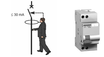
Figure 6: Active Protection Measure for People with a Differential Device, with a Stipulated Residual Current Not Exceeding 30mA.
Protection of Persons Against Indirect Contact
The protection of persons against indirect contact is directly associated with the Grounding Scheme Meth-odologies (ELT) adopted in LVEIs. These methodologies are also sometimes called Neutral Regimes, as they are associated with how the Neutral is used in the implementation of the protection system. In the context of protecting persons against indirect contact, there are two levels of protection:
• 1st level: grounding of all conductive masses of electrical equipment, constituting an equipotential circuit;
• 2nd level: automatic interruption of the electrical supply to the faulty section of the installation. The operating time of the interruption device obeys specific requirements according to the amplitude of the fault voltage.
Conductive masses are metallic elements of electrical installations and equipment that, in the absence of any insulation fault, do not present any electrical potential. An indirect contact is represented in Figure 7, where Uc is the voltage of the indirect contact to which the person is subjected. In this case, it is observed that the current does not circulate entirely through the human body, and the value of the fault current will depend on the UL (Electrical Voltage Limit) adopted for the electrical installation.

Figure 7: Electrical Diagram of Indirect Contact: Electrical Contact of a Person with a Body Accidentally Placed under Voltage [3].
The protection of people against indirect contact can be achieved by automatically disconnecting the power supply, provided that all conductive masses are properly placed at earth potential. The way this is done defines the ELT adopted in the installation. Thus, ELTs are characterized by:
• The grounding method of one of the power supply points, generally the neutral;
• The means of grounding the masses of the utilization equipment.
The ELTs adopted in LVEIs are the TT scheme, the TN scheme and the IT scheme. The meaning of the dif-ferent letters, according to the IEC 60364-3-1 standard, is as follows [3,20]:
• First letter - Power supply situation in relation to earth:
T – direct connection of a point to earth;
I – isolation of all live parts in relation to earth, or connection of a point to earth by means of an impedance.
• Second letter – Situation of the installation’s masses in relation to earth:
T – masses connected directly to earth, regardless of the eventual grounding of a point of the power supply;
N – electrical connection of the masses to the grounded power supply point (in alternating current, the grounded point is, as a rule, the neutral point or, if this is not accessible, a phase conductor).
• Arrangement of the neutral conductor and the protective conductor:
S – neutral and protective functions guaranteed by separate conductors (N conductor and PE conductor); this is the case of the TN-S system:
C – neutral and protective functions combined in a single conductor (PEN conductor); this is the case of the TN-C system.
The choice of the ELT conditions the adoption of measures to protect people against indirect contact. In terms of people safety criteria, the three ELTs are equivalent if all rules are respected. It is imperatives of service continuity and operational conditions of the installation that determine the choice(s) of ELT, sometimes also called neutral regimes. An insulation fault in equipment causes a current to circulate, which must be interrupted in a time compatible with the safety of people. The protection measure is based on the automatic interruption of the power supply and the association of the following conditions:
• The realization or existence of a circuit called a fault loop, which allows the circulation of the fault current, the constitution of this loop depending on the ELT (TT, TN or IT) adopted in the installation;
• The interruption of the fault current is carried out by an appropriate protection device, in a time that depends on parameters such as contact voltage and classification of the location regarding external influences, associated with knowledge of the effects of electric current on the human body (Figure 2).
The IEC 60364-4-41 standard [3,19] specifies the maximum operating times of indirect contact protection devices. With regard to safety, all ELTs are equivalent, provided that the rules inherent to each one are not neglected. However, there are special situations:
• The case of hospital operating rooms, where cutting off the first fault is unthinkable. In this case, the only possible scheme is the IT scheme.
• Computer centers, where leakage currents are high, the recommended scheme is the TN scheme.
• Installations where the length of the piping is unknown and locations with a risk of explosion, the TT scheme will be the most suitable.
Grounding Scheme: TT
In this grounding system, all the exposed conductive parts of electrical equipment protected by the same protective device must be interconnected by means of protective conductors and connected to the same grounding electrode. At the same time, the neutral point of the power supply must be grounded, or if this does not exist, one phase. This system is shown in Figure 8, where RB is the resistance of the power supply grounding electrode and RA is the resistance of the grounding electrode of the exposed conductive parts of the installation.

Figure 8: TT Grounding Scheme [20]
Currently, electrical installations directly powered by a (public) low-voltage (LV) power distribution network are, for the time being, only carried out according to the TT scheme. In this scheme, faults between phase and ground cause a fault current to circulate in the loop, which closes through the ground. The impedance of this fault loop, consisting essentially of the resistances of the grounding electrodes of the masses and the supply (neutral), limits the value of the fault current, which in practice makes it impossible to guarantee the protection of people against indirect contact with traditional overcurrent protection devices (circuit breakers and fuses).
Figure 9 illustrates the loop through which the fault current flows when there is a fault between a phase and the ground of a device powered by a three-phase network. As a rule, the sum of the resistances of the grounding electrodes of the masses and the power supply (RA+RB) is much greater than the impedance of the other elements of the mesh, so that the total impedance of the mesh is practically equal to (RA+RB).

Figure 9: TT Scheme: Fault Loop Path [3].
The presumed contact voltage for the fault will be :

Where:
Uc: fault contact voltage with ground (V);
U0: simple supply voltage (V);
RA : resistance of the grounding electrode of the installation’s masses (Ω);
RB: resistance of the grounding electrode of the installation’s supply (Ω);
In this TT system, the following protection devices must be used for automatic power cutoff:
• Differential devices (preferably);
• Overcurrent protection devices, only when the resistances of the grounding electrodes have very low values (solution that has little practical applicability).
According to international standards, differential devices (devices sensitive to residual fault current) are grouped by “sensitivities,” associated with the value of their stipulated differential current (IΔn). The sensitivity of the differential device must satisfy the following condition.

where the value to be considered for the conventional limit voltage (UL) depends on the classification of the locations regarding external influences.
The sensitivity value of the differential device is indifferent to the value of the resistance of the power supply grounding electrode (RB), depending only on the type of location (UL) and the resistance of the mass grounding electrode (RA). From equation (2) and, if there are no other constraints, it is also possible to obtain the maximum permissible value for the resistance of the mass grounding electrode (RA) as a function of the highest value of the stipulated differential current (IΔn), adopted in the differential devices of the different circuits of the electrical installation. Thus, there are tables that indicate the maximum values of the grounding electrode resistance of the masses, so that the contact voltage (Uc) does not exceed the conventional limit voltage in alternating current installations (UL=25 V or UL=50 V, depending on the (IΔn). The sensitivity of the differential device must satisfy the classification of the location regarding “external influences”, as a function of the highest value of the stipulated differential current (IΔn) to be used in the differential device.
In order for the contact voltage not to reach values that are dangerous to people, it must be lower than the conventional limit voltage specified for the installation location. The operating time of the protection device must be very fast and must comply with current regulations, in order to avoid pathophysiological effects of electric current on humans, as presented in sections 2 and 3. The calculation procedure for the differential device should be based on the following:
Where:
Uc: fault contact voltage with ground (V);
UL: conventional limit voltage at the installation site (50 V or 25 V);
RA: resistance of the grounding electrode of the installation’s masses (Ω);
Id: current flowing in the fault loop (A);
IΔn: rated current of the differential protection device (A) The IEC 60364-4-41 standard specifies the maximum operating time of indirect contact protection devices in the TT system. For final circuits with a rated current not exceeding 32 A, the operating time should not exceed 0.2 s. In all other circuits, the operating time should not exceed 1 s, and selectivity between differential devices in the same distribution circuit must be guaranteed.
According to the same IEC 60364-4-41 standard, high-sensitivity devices (30 mA) should be used for the protection of people in electrical systems powered by sockets with a rated current of less than 20 A.
The use of high-sensitivity devices is also recommended for the protection of people in electrical installations considered special, such as: Damp locations, Temporary electrical installations powered by sockets, laundries and swimming pools, caravans, recreational boats, mobile installations, fairs.
Grounding Scheme: TN
This ETL is characterized by all the masses of the installation being connected to the grounded point of the power supply, near the transformer or generator supplying the installation, by means of protective conductors.
The grounded point of the power supply is, as a rule, the neutral point. If there is no neutral, a phase conductor must be grounded, and under no circumstances may this conductor be used as a PEN conductor. In installa-tions directly supplied by a (public) low-voltage distribution network, it is not currently possible to use the TN system in low-voltage electrical power installations.
The measures to protect people against indirect contact in this ELT can be carried out in the following ways:
TN-C: the functions of the neutral conductor (N conductor) and the protective conductor (PE conductor) are combined into a single conductor (PEN conductor) throughout the diagram, as shown in Figure 10 [20];

Figure 10: TN-C Grounding Scheme [20].
TN-S: the functions of the neutral conductor (N conductor) and the protective conductor (PE conductor) are distinct throughout the system, as shown in Figure 11 [20];

Figure 11: TN-S Grounding Scheme. With and without the Presence of a Neutral in the Supply [20].
TN-C-S: the functions of the neutral conductor (N conductor) and the protective conductor (PE conductor) are combined into a single conductor (PEN conductor) in one part of the installation and are distinct in the rest of the installation (N conductor and PE conductor), as shown in Figure 12.

Figure 12: TN-C-S Grounding Scheme [20].
In fixed installations, a single conductor can be used for both protective and neutral conductor functions (designated as a PEN conductor), provided that the protective conductor has a cross-section of at least 10 mm² if made of copper, or 16 mm² if made of aluminum, and the common part of the installation (TN-C system) is not located downstream of a differential device.
The TN-C and TN-S systems can be used in the same installation as long as the TN-C system is upstream of the TN-S system (in which case they constitute the TN-C-S system). In practice, this is the most commonly used grounding system in installations where the TN system is adopted, since, as a rule in these installations, the distribution circuits (supply to electrical panels) have conductors with a cross-section of at least 10 mm², with the final circuits obviously having a smaller cross-section. The connection of the exposed conductive parts to the neutral conductor depends on the system used.
In the TN-C system, the connection of the exposed conductive parts to the PEN conductor must be made at easily accessible points, which must allow for insulation measurements (in accordance with current legislation). To avoid any risk of interruption of the PEN conductor, this conductor must have a sufficient cross- section, from the point of view of mechanical resistance, which is guaranteed by the standardized minimum cross-sections defined for this conductor (10 mm2). In reality, interruption of the PEN conductor could expose the exposed conductive parts of the equipment to the phase-to-earth voltage of the installation, which, if the installation were powered at 230/400 V, reaches values incompatible with the safety of people, where the contact voltage (Uc) would reach approximately 230 V.
In the TN-S system, the protective conductor must be connected to the neutral conductor at the origin of the installation (normally, the “entry panel” of the electrical installations). Usually, in the TN system, the final circuits are made according to the TN-S scheme (since they have a cross-section of less than 10 mm2, if copper, or 16 mm2, if aluminum).
The flexible cables used as mobile conduits must have a protective conductor distinct from the neutral con-ductor, regardless of the scheme (TN-C, TN-S or TN-C-S) used in the fixed installation that feeds them.
In any of the TN systems adopted in the installation, any insulation fault to earth results in a phase-to-neutral short circuit. Figure 13 shows the fault loop in a TN-C scheme.
Since the short-circuit current reaches very high values, automatic power disconnection can be ensured by overcurrent protection devices, or devices sensitive to residual differential current, if the fault current is not high enough.
The determination of protection conditions can be done as follows:
• By calculation, when the protective conductor (PEN in the TN-C system and PE in the TN-S system) is, throughout the installation, located in the immediate vicinity of the active conductors of the corre-sponding circuit, without the interposition of ferromagnetic elements (most usual situation);
• By measurement, in the case where the previous conditions are not met, where it is practically impossible to determine, by calculation, the impedance of the fault loop and its value can only be known by re-sorting to measurements after the installation has been carried out.
In this ELT, an insulation fault is similar to a phase-to-neutral short circuit, and the interruption must be ensured by the short-circuit protection device, with a specified maximum interruption time that is a function of the conventional limit voltage (UL) admissible for the installation location, i.e., 25 V or 50 V in alternating current, the value being defined by the classification of the location regarding external influences.
According to the IEC 60364-4-41 standard [18], the interruption time of the protection device should be 0.4 s for UL=50 V and 0.2 s for UL=25 V.
To be sure that the protection is actually active, it is necessary that, whatever the location of the fault, the fault current Id is greater than the threshold value stipulated for the protection device Ia (Id > Ia). This condition must be verified when designing the installation, by calculating the fault currents and for all distribution circuits. The fact that the live conductors and the protective conductor have the same path simplifies this calculation.
When the impedance of the power supply and cables has a high value, differential protection devices should be associated with short-circuit protection devices. The use of differential devices has the advantage of making it unnecessary to check the impedance of the fault loop, an advantage that is particularly interesting when the installation is modified or expanded. Obviously, this solution cannot be adopted in the TN-C system, in which the protective conductor is confused with the neutral conductor. From the above, when it is necessary to use differential devices in the TN system, devices with high sensitivity of stipulated differential current (30 mA or 300 mA) are not recommended, due to the possibility of untimely tripping, which generally has serious con-sequences due to the interruption of service continuity in installations that use this earthing system. In these installations, low-sensitivity devices (IΔn >1 A) are recommended, provided, however, that the contact voltage values do not exceed the conventional permissible voltage limit for the installation location.
Grounding Scheme: IT
This earthing system (ELT) is characterized by all active parts of the installation being isolated from earth, or reconnected through a sufficiently high impedance, and the masses of the user installation being directly connected to earth. Figure 14 shows the ELT in IT, in situations with and without the distributed neutral.
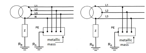
Figure 14: IT Grounding Scheme, with and without Distributed Neutral Conductor [20].
This ELT main advantage is the guarantee of service continuity in the presence of a first insulation fault. Thus, all situations that could contribute to decreasing the system’s reliability must be eliminated. As a result, dis-tributing the neutral conductor in this ELT is not recommended.
When a single fault occurs and all the rules relating to the IT scheme are met, the interruption is not “man-datory” since the resulting fault current is of reduced value, and the contact voltage will always be less than the conventional limit voltage specified for the installation location. The fault current circuit in the situation of a first fault is shown in Figure 15. It can be seen that the current of a first fault is limited by the impedance Z, normally a resistance that can vary between 1000 Ω and 1500 Ω, and the leakage impedance of the installation, typically capacitive, with an approximate value of 1 μF/km. The figure also shows the Permanent Insulation Controller (CPI) and the surge limiter.

Figure 15: First Fault Loop in an IT type ELT [3].
However, if a second fault occurs without the first having been resolved, appropriate measures must be taken to avoid the risk of dangerous pathophysiological effects for people (sections 2 and 3) who may come into contact with simultaneously accessible conductive parts. Although in the case of a first fault, disconnection is neither “mandatory” nor desirable, the fault must be investigated and resolved before a second fault occurs, where the fault current would reach very high and dangerous values, making disconnection “mandatory” in this situation. In this case, the power supply is interrupted, which could have serious consequences (for example, in operating room installations, in “medical use areas”). Monitoring and signaling the existence of a first fault in the installation is carried out using a Permanent Insulation Controller device (Figure 16), which is mandatory in installations that adopt this ELT.

Figure 16: Permanent Ground Isolation Controller. (Source: Schneider Electric)
Figure 17 shows the fault loop path for a first fault (blue), and the fault loop path for a second fault without the first one being resolved (red).
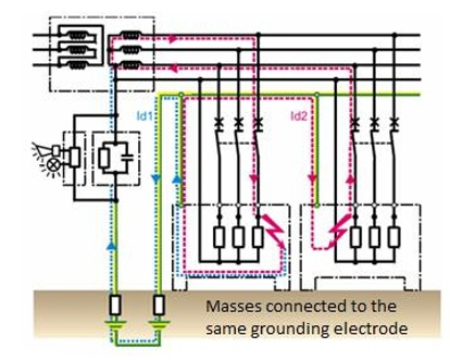
Figure 17: Second Fault Loop, or Double Fault Loop. (Source: Schneider Electric)
The method of eliminating a second fault depends on how the masses are connected to earth:
• If all masses, including those of the source, are connected to the same earthing electrode (common situation in IT system installations). The installation system (IT) becomes a situation similar to the TN system, but with a double fault loop. Protection is guaranteed by the same conditions indicated for the TN system (Figure 17);
• If the masses are earthed, individually or in groups, the installation system (IT) becomes a situation similar to the TT system. Protection is then guaranteed by the same conditions indicated for the TT system (Figure 18).
Figure 18: Second Fault Loop, or Double Fault Loop. (Source: Schneider Electric)
In this ELT the protection of people against indirect contact is ensured by the use of the following monitoring and protection devices:
• Permanent Isolation Controllers (CPI). Although primarily intended for monitoring the first fault, these devices can also be used as protection devices in situations where it is necessary
• Overcurrent protection (circuit breakers and fuses). These devices are used in situations where, upon the second fault, the protection conditions defined for the TN system are applied to them (Figure 17);
• Differential devices. These devices are used in situations where, upon the second fault, the pro-tection conditions for the TT system are applied to them (Figure 18).
• Differential devices can be used as a backup measure when overcurrent protection devices do not guarantee protection. The response time of personal protective equipment must be fast enough to avoid the pathophysiological effects discussed in sections 2 and 3 of this document, which can be seen in Figure 2.
These response times are defined normatively (IEC 60364-4-41) and depend on the ELT adopted in the installation. As a rule, they should never exceed 1 second.
Conclusions
Electrical accidents cause various pathophysiological effects and consequences in the human body. The spectrum ranges from asymptomatic to severe injuries due to burns and cardiorespiratory arrest. The severity of an electrical injury depends on the energy applied and the path of the current through the body, which is not always predictable [12]. Burns are a global health problem and, when caused by electricity, represent a par-ticular challenge, since assessing their severity based on the area of the body surface affected is unreliable, as deep lesions and systemic consequences may be present [12]. The best “treatment” for electrical injuries is prevention. Efforts to prevent workplace accidents in high-risk professions and domestic accidents involving children are essential. Many recommendations involve implementing workplace safety procedures. Examples include periodic inspections of electrical installations, de-energizing power lines before work begins, main-taining the required safety distance from power sources, and hazard recognition training. In the event of an accident, the magnitude of the electric current passing through the body must be minimized through measures to increase resistance, such as the use of flame-retardant protective clothing, non-conductive ladders or in-sulating blankets, and automatic power cut-off mechanisms (circuit breakers, fuses, and safety devices sen-sitive to residual fault current). Thus, standardized response measures and optimized incident management are important, as is training and the availability of resuscitation equipment through simulations, cardiopulmonary resuscitation training, proximity warning devices for equipment and live parts with high electrical potentials, and the wide availability of defibrillators in public places [7].
With regard to domestic accidents, electrical installations must comply with current safety standards. Edu-cating and supervising children is essential. The use of socket protectors, the removal of exposed wires, and avoiding the use of electrical appliances with wet skin are crucial preventive measures. The protection offered by many modern electrical installations (such as switches and circuit breakers sensitive to residual current) limits the duration of exposure and the intensity of the transmitted current, resulting, in most cases, in accidents without serious consequences. It is important not to neglect the role of public awareness campaigns in promoting a better understanding of the risks involved, as well as the correct approach to be adopted in these cases [7]. Medical care is essential for early assessment and guidance on the effects associated with electric shock. This narrative review seeks to analyze the main injuries to be considered after these accidents, with proper examination and follow-up being essential tools. As several organs and systems of the human body are affected, a multidisciplinary approach is necessary.
The flow of current in electrical installations always entails risks. In all electrical installations, there is a need and obligation to implement effective protection systems, aiming at their operation under safe conditions. In Low Voltage Electrical Installations (LVEI), measures to protect people from the risk of electrification and electrocution take on additional importance in order to avoid pathophysiological effects that may be irre-versible.
In electrical installations, poorly insulated appliances, wiring defects, or incorrect use of equipment can cause significant hazards in terms of equipment (fires) and people (electrocution). Thus, according to the charac-teristics and purpose of the electrical installations, different Grounding Schemes (ELT), TT, TN, and IT are adopted.
ELT, or neutral systems, characterize:
• The grounding method of one of the power supply points, generally the neutral;
• The means of grounding the masses of the equipment in use.
The choice of ELT conditions the measures for protecting people against indirect contact. In terms of personal safety criteria, the three neutral systems are equivalent if all the installation rules are respected. It is imperatives of service continuity and operating conditions that determine the choice(s) of the ELT (or neutral system).
This document details the pathophysiological effects of electric current on different organs of the human body.
A detailed explanation was given of how to protect people, users of low-voltage electrical installations and equipment, from the risks of direct contact and, fundamentally, from indirect contact with equipment masses that, due to deficiencies or defects in insulation, are energized.
Author Contributions: Conceptualization, José Carvalho and Maria Almeida; methodology, José Carvalho.; validation, all authors; formal analysis, all authors; writing—original draft preparation, all authors; writ-ing—review and editing, José Carvalho and Maria Almeida. All authors have read and agreed to the published version of the manuscript.
Funding: This research received no external funding. Data Availability Statement: Datasets are available upon request to the authors.
Conflicts of Interest: The authors declare no conflict of interest.
References
- Hörburger, D., Schmidt, E. & Henz, S. Stromunfälle. Praxis.
- Neurological and neurourological complications of electrical injuries | Yiannopoulou | Neurologia i Neurochirurgia Polska.
- Electrical installation guide 2018: Protection against electric shocks and electrical fires. Schneider Electric, 2019.
- Friedstat, J., Brown, D. A., & Levi, B. (2017). Chemical, electrical, and radiation injuries. Clinics in plastic sur-gery, 44(3), 657.
- Shahid, F., Gondal, M. F., Sabah, N. U., Chaudhry, R., Aslam, H., Iftikhar, U., ... & Basit, J. (2022). Psychosocial impact of electrical burn in children: a follow-up study conducted at a tertiary care hospital. Cureus, 14(12), e32816.
- Stockly, O. R., Wolfe, A. E., Espinoza, L. F., Simko, L. C.,Kowalske, K., Carrougher, G. J., ... & Schneider, J. C. (2020). The impact of electrical injuries on long-term outcomes: A Burn Model System National Database study. Burns, 46(2), 352-359.
- Waldmann, V., Narayanan, K., Combes, N., Jost, D., Jouven, X., & Marijon, E. (2018). Electrical cardiac injuries: current concepts and management. European heart journal, 39(16), 1459-1465.
- Lee, D. H., Desai, M. J., & Gauger, E. M. (2019). Electrical injuries of the hand and upper extremity. JAAOS-Journal of the American Academy of Orthopaedic Surgeons, 27(1), e1-e8.
- Favia, M., Mele, F., Introna, F., & De Donno, A. (2021). Morphological cardiac changes in electrocution deaths: A literature review. Medicine, Science and the Law, 61(1_suppl),130-135.
- Upon admission coagulation and platelet function in patients with thermal and electrical injuries - PubMed.
- Albert, T., Perrot, P., Lecoq, F. A., & Lancien, U. (2025). Post-burn carpal tunnel syndrome: A systematic re-view. Hand Surgery and Rehabilitation, 44(3), 102134.
- Ye, Z. J., & Huang, Y. C. (2025). Liver laceration from electrical burn, a case report and literature review. The American Journal of Emergency Medicine, 99, 436-438.
- Kærgaard, A., Nielsen, K. J., Carstensen, O., & Biering, K. (2023). Electrical injury and the longâ?term risk of cataract: A prospective matched cohort study. Acta ophthalmologica, 101(1), e88-e94.
- Kang, S., Kufta, K., Sollecito, T. P., & Panchal, N. (2018). A treatment algorithm for the management of intraoral burns: a narrative review. Burns, 44(5), 1065-1076.
- Khor, D., AlQasas, T., Galet, C., Barrash, J., Granchi, T., Bertellotti, R., & Wibbenmeyer, L. (2023). Electrical injuries and outcomes: a retrospective review. Burns, 49(7), 1739-1744.
- Wesner, M. L., & Hickie, J. (2013). Long-term sequelae of electrical injury. Canadian Family Physician, 59(9), 935-939.
- Caballero-Carvajal, J. A., Manrique-Hernández, E. F., Becerra-Ar, C., & Alvarado-Socarras, J. L. (2020). Secondary maternal–fetal consequences to electrical injury: A literature review. Taiwanese Journal of Obstetrics and Gyne-cology, 59(1), 1-7.
- Einarson, A., Bailey, B., Inocencion, G., Ormond, K., & Koren, G. (1997). Accidental electric shock in pregnancy: a prospective cohort study. American journal of obstetrics and gynecology, 176(3), 678-681.
- Carvalho, J., Almeida, M., Silva, C., & Costa, C. (2026). Physiopathological Effects of Electric Current on the Human Body and the Protection Against Electric Shocks.
- “Regras Técnicas das Instalações Elétricas de Baixa Tensão”- (Decreto-Lei n.º 226/2005 de 28 de dezembro).