
Open Access Journal of Applied Science and Technology(OAJAST)
ISSN: 2993-5377 | DOI: 10.33140/OAJAST
Impact Factor: 1.08


Short Communication - (2025) Volume 3, Issue 3
Introduction and Analysis of Parameters of a New Curve for Use in Roadway Geometric Design
2Department of Civil Engineering, School of Engineering University of Tehran, Tehran, Iran
3Department of Civil and Environmental Engineering, University of Delaware, Newark, Delaware, 19716, United States
Received Date: Sep 02, 2025 / Accepted Date: Oct 17, 2025 / Published Date: Oct 21, 2025
Copyright: ©2025 Abolfazl Taherpour, et al. This is an open-access article distributed under the terms of the Creative Commons Attribution License, which permits unrestricted use, distribution, and reproduction in any medium, provided the original author and source are credited.
Citation: Taherpour, A., Ghadermazi, E., Jeihani, M., Nozari, M. A. (2025). Introduction and Analysis of Parameters of a New Curve for Use in Roadway Geometric Design. OA J Applied Sci Technol, 3(3), 01-06.
Abstract
Commonly used curves in roadway design include simple curves, multi-centered compound curves, and clothoid curves. The most critical parameter of any curve is its radius of curvature, which depends on factors such as design speed and parameters like friction and superelevation. This paper introduces a new curve that is similar to a clothoid, where the radius of curvature varies across points on the curve. However, it differs in its mathematical formulation and construction methodology. This curve enables a linear increase or decrease in curvature, making it suitable for ramps and sections where entry and exit speeds differ or where continuous changes in curvature are required. The paper derives the geometric characteristics of this curve and explores its potential applications in roadway design. Parameters such as enclosed area and length of the curve are calculated and compared with conventional compound curves. The findings of this study highlight the advantages of the proposed curve as an alternative to multi-centered compound curves in roadway design. Its performance in linear transition, coupled with its straightforward implementation, makes it a promising candidate for practical applications.
Keywords
New Curve, Clothoid, Curve Length, Radius of Curvature, Compound Curve
Introduction
Horizontal curves in roadway design are utilized to change the direction of roads and to provide a smooth connection between two intersecting roadways. Several types of curves are employed for implementing these connections, each with unique geometric properties. The simplest of these are circular curves, characterized by a single center and radius, which function to connect and redirect sections of the road. The most critical parameter of any curve is its radius of curvature, as it directly influences the centripetal acceleration exerted on vehicles and determines the permissible safe design speed of that section of the road.
Intersections and interchanges inherently involve angles between connecting roadways. To design appropriate transitions, it is nec- essary to utilize suitable curves. Simple circular curves are often insufficient for connecting roads with different design speeds, leading to the use of alternatives such as multi-centered compound curves and clothoid curves. When connecting a straight path to a circular curve, sudden lateral acceleration (caused by centripe- tal force) can occur. To mitigate this, designers employ transition curves, which gradually introduce lateral acceleration over an ap- propriate distance. Transition curves also allow for the gradual ap- plication of superelevation, avoiding abrupt changes in the straight segment and ensuring the design remains safe and efficient [1]. Some of the most commonly used transition curves in roadway and railway are as follows:
Clothoid
Known as a spiral or Euler spiral, the clothoid curve is one of the most widely applied transition curves due to its spiral shape. Its curvature increases proportionally with the distance traveled along the curve. Since superelevation is proportional to the curve's curvature, superelevation also changes progressively along the clothoid, making it ideal for safe and comfortable transitions [1]. The advantages of using clothoid curves in road design include the gradual increase in centripetal force, ease of transition execution, and the aesthetic appeal they provide to the roadway. Although most design standards recommend clothoid curves, some studies highlight potential drawbacks, such as safety risks associated with longer curves and a lack of uniformity in certain applications [2-6].
Lemniscate
Also known as the Bernoulli lemniscate, this curve has a cloverleaf shape with its curvature varying based on the length of its radius vector rather than arc length. It is simpler to implement than clothoids due to its straightforward mathematical properties [1].
Parabolic Curves
Parabolic curves of degree three or higher can serve as transition curves. However, third-degree parabolic curves are limited to the segment between the origin and the point of maximum curvature, which poses a disadvantage. Higher-degree parabolic curves are rarely used due to this limitation [1].
Maloid Curves
Similar to third-degree parabolas, Maloid curves have a point of maximum curvature and are primarily used for steep, mountainous roads where sharper angles and smaller radii are common. These curves are often applied in serpentine sections. While clothoid and lemniscate curves are versatile and suitable for various scenarios, Maloid and parabolic curves are typically reserved for specific cases. For sharp turns and small radii, Lemniscate or clothoid curves are generally recommended, while Maloid curves are best for large deflection angles [1].
Multi-Centered Compound Curves
These curves are employed to connect straight segments to other curves. For example, a clothoid starts with an infinite radius, re- sulting in zero initial lateral acceleration that gradually increases with the curve's length. Once the vehicle adapts to the new cur- vature, a simple circular curve may follow. A common approach in ramp design is the combination of clothoid curve-compound curve-clothoid curve. However, this approach can lead to abrupt changes in curvature between segments, introducing sudden cen- tripetal acceleration [1].
The proposed curve in this paper addresses these challenges. Unlike traditional multi-centered compound curves, where radii change abruptly in a stepwise manner, the new curve reduces or increas- es curvature linearly and continuously, avoiding sudden changes in centripetal acceleration. Although clothoids still perform better in connecting straight segments to curves, the proposed curve of- fers a compelling alternative for intermediate segments in ramps, replacing multi-centered compound curves effectively. It should be noted that the curves that were briefly introduced have a long history in technical literature, and recent references and articles have mostly dealt with safety and traffic issues and optimization of existing curves. Therefore, regarding the proposed new curve, no direct reference has been found.
The subsequent sections delve into the mathematical framework of the proposed curve, detailing its geometric parameters and prop- erties. They also include calculations of the curve’s length and the enclosed land area in polar coordinates, providing a compre- hensive understanding of its spatial characteristics. Additionally, practical implementation guidelines are presented for designing intersections with varying radii and deflection angles. Finally, a comparative analysis is conducted, highlighting the advantages of the proposed curve over multi-centered compound curves.
Introduction of the New Curve
Drawing Method
The concept for constructing this curve originates from observing the motion of a string wrapped around a circular object, where the string’s length decreases continuously as it unwinds. Imagine a string of length (l) tied to a point on the circumference of a circle with the radius (r). The curve traced by the endpoint of the string, while fully stretched and moving around the circle, forms the pro- posed curve (Figure 1a). As the endpoint moves around the circle, more of the string wraps around the circle, leading to a gradual reduction in the radius of curvature.
In this configuration, the radius of curvature decreases linearly with the string's angle of rotation (θ), while the remaining portion of the string stretches tangentially to the circle. The geometric co- ordinates of this curve are derived based on the relationship be- tween the circle’s radius (r), the string length (l), and the angular displacement (θ).
Mathematical Properties
The goal is to determine the coordinates of any point M on the curve as a function of the angle (θ) in radians, with known values of (r) (circle radius) and length (l) (string length). The origin of the coordinate system is assumed to be the center of the circle at O (0,0) (Figure 1b). Figure (1) shows the initial idea for constructing the curve and geometrical parameters.
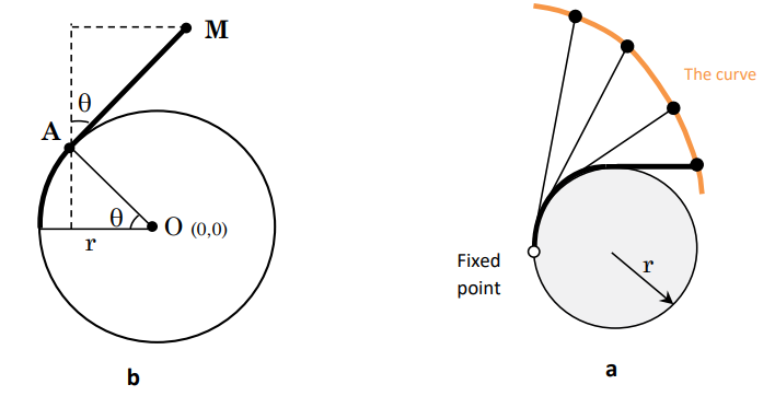
Figure 1: The Initial Idea of the New Curve and Geometrical Parameters
Curve Length
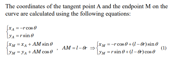
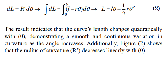
The length of the curve is a crucial geometric parameter in roadway design. For a small segment of the curve, the geometric properties are illustrated in Figure (2). Using polar coordinate relations, the total length of the curve as a function of (θ) is calculated by integrating the curve’s elements. Equation (2) indicates the length of the small segment of the curve.
Figure 2: Length and Area Differentials for Integration
The Area Enclosed by the Curve
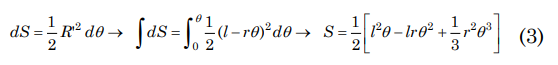
Calculating the area enclosed by the curve is critical for determining the land use required in roadway design. Figure (2) depicts an infinitesimal area element dS, which can be used to compute the total enclosed area using polar coordinate integration. Equation (3) provides the total land use as a function of the string length (l), circle radius (r), and rotation angle (θ).
Implementation of Curve at Intersection
This section describes how to draw and implement the introduced curve for an arbitrary intersection. The lines assumed as straight paths can also be used in any other part of the road where a change in radius is needed. For example, these lines could be ending tangents to clothoids that are themselves connected to straight paths.
For simplicity, it is assumed that this curve is used at the intersection of two roads with design speeds V1>V2 and an intersection angle Δ in radians. For ease of calculation, one of the roads is aligned with the horizontal axis, and the origin of the coordinates is placed at the intersection of the two roads. Given the design speeds, maximum superelevation rates, and side friction coefficients for these two paths, radii R1 and R2 are calculated using equation (4). If this curve is used to continue the clothoid path, R1 and R2 will be the same as the end radii of the clothoids.
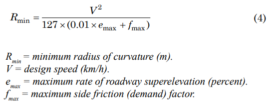
First, it is necessary to determine the center and radius of the circle introduced in previous sections, based on which the curve is drawn. Since the mathematical coordinates of the curve were obtained assuming that the origin of the coordinates is at the center of this circle (Equation 1), it is necessary to vector-add the new coordinates of the circle center with the coordinates of points on the curve to draw the curve by changing the origin of coordinates to the intersection of the two paths. Figure (3) illustrates how the curve connects the two paths, with the deflection angle Δ and radii R1 and R2 explicitly defined.
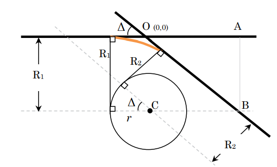
Figure 3: Constructing the Curve for an Intersection
Coordinates of the circle center: Using the tangents and consid- ering that the tangent is perpendicular to the radius at the point of contact, the center of the circle is obtained from the intersection of the dashed lines (Figure 3). The mentioned dashed lines are at dis- tances R1 and R2 from the first and second roads. The coordinates of point C can be determined using equation (5).
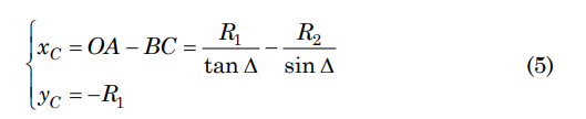
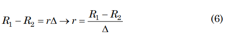
Calculation of the circle radius: Given that the radius of curvature of the curve at the beginning of the path will be R1 and at the end of the path R2, the difference between these two radii should be wrapped around the circle. This difference covers an arc of the circle that faces the angle Δ. See equation (6).
With the center and radius of the circle obtained in terms of the design radii and the angle between the two roads, drawing the curve using equations (1), (5), and (6) will be possible. It should be noted that the above equations were calculated for the case R1>R2. In the case where R2 is larger, there is no need to change the equations. The circle radius just becomes a negative number, which, although lacking physical meaning, substituting this negative number in equation (1) for calculating the coordinates of the curve yields the correct values.
Comparison of the Proposed Curve with Multi-Centered Compound Curves
One of the key strengths of the proposed curve is its continuous variation in the radius of curvature. Figure (4) qualitatively compares the radius of curvature for three types of curves: the clothoid, the multi-centered compound curve, and the proposed curve. While clothoids and the proposed curve feature smooth and continuous transitions in curvature, multi-centered compound curves exhibit abrupt changes in radius, resulting in sudden centripetal accelerations.
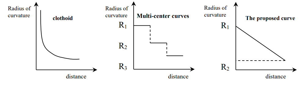
Figure 4: The Radius of Curvature as a Function of Distance for Three Types of Curves
In the following, we compare the introduced curve with a simple two-centered curve. For this purpose, we examine the connection of two roads with design radii R1>R2 that intersect at an angle Δ (in radians) using these two curves. Two fundamental road design parameters, namely length variations and the occupied area of these two curves, are compared.
Length of Curves
Considering that in a two-centered curve, it is necessary to divide the angle Δ into two parts Δ1 and Δ2, and the determination of these values depends on the designer's opinion, this paper also examines the two-centered curve with different angle ratios. To compare the lengths of the two curves, using equations 2 and 6, the equation for the length of the proposed curve in terms of angle Δ is obtained in equation (7).
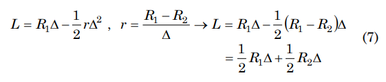
Also, the arc length for the two-centered curve is obtained from the simple arc length formula using equation (8).
It can be observed that if we divide the angle Δ into two equal parts for drawing the two-centered curve, the length of the two-centered curve will be equal to the proposed curve for any angle and radius.
Occupied Area of the Curves
The land use for each curve is calculated based on the area enclosed by the curve and the adjacent straight paths. For the proposed curve, the area is computed using Equation (3). For the compound curve, the land use is calculated geometrically by segmenting the region into subareas corresponding to its arcs.
A comparative plot of the land use for the proposed curve and two-centered compound curves, shown in Figure (5), indicates noticeable differences depending on the design parameters. For smaller deflection angles, the proposed curve tends to require less land use. It should be mentioned that radii R1=250m and R2=80m are assumed to draw the plot.

Figure 5: Land Use of the Proposed Curve vs Two-Center Compound Curves
Conclusion and Recommendations
Conclusion
Various curves are employed in roadway design, each with unique characteristics and equations. Among these, the radius of curvature is the most critical parameter, as it directly affects the centripetal acceleration experienced by vehicles during directional changes. Curves that ensure smooth and continuous transitions in radius are particularly valuable in roadway design. Transition curves, such as clothoids, are widely used for this purpose because they provide a continuous variation in curvature. The proposed curve in this paper demonstrates behavior similar to clothoids in terms of smooth curvature transitions. However, unlike the clothoid, the proposed curve starts with a finite radius of curvature. This means that when connecting the curve to a straight path, the centripetal acceleration begins suddenly, making clothoids superior for such applications.
In other scenarios, such as ramps or transitions that currently use multi-centered compound curves, the proposed curve can serve as a viable replacement. The proposed curve eliminates the abrupt changes in curvature associated with compound curves, thereby improving both safety and passenger comfort. This paper has thoroughly described the mathematical properties of the proposed curve, including its equations, length, and enclosed land use. It also outlined its implementation for connecting two intersecting roads with different radii and deflection angles. The simplicity of the curve’s equations for calculating length and land use is a key advantage compared to clothoids.
A comparative analysis of the proposed curve and a two-centered compound curve revealed fundamental similarities in their lengths when the deflection angle is evenly divided. However, differences in land use were observed, with the proposed curve demonstrating superior performance in certain scenarios. Given the proposed curve’s characteristics, it is logical to recommend replacing multi- centered compound curves with this new curve. The proposed curve addresses the drawbacks of compound curves while retaining simple mathematical formulations.
Recommendations
While this paper has primarily focused on the mathematical properties of the proposed curve, further studies are recommended to explore its practical applications in roadway design. Potential future research directions include:
• Safety and Sight Distance Analysis: Detailed studies on how the proposed curve impacts sight distance and driver safety, particularly in high-speed conditions.
• Comparative Land Use Studies: Further evaluation of land use for the proposed curve compared to other roadway curves, such as three-centered compound curves and clothoids, to identify its advantages and limitations.
• Explicit Equation Development: Deriving explicit equations for the proposed curve facilitates easier implementation in design software and real-world projects.
• Field Implementation: Experimental application of the proposed curve in a real-world ramp or intersection. This could involve studying passenger comfort, vehicle dynamics, and crash risks to validate the the- oretical findings.
The proposed curve shows significant potential as an alternative to multi-centered compound curves, particularly in applications requiring smooth transitions. Future research and practical appli- cations will further uncover its benefits and expand its utility in roadway design.
Funding
This research was supported by the Safety and Mobility Advancements Regional Transportation and Economics Research (SMARTER) Center at Morgan State University and the University Transportation Center(s) Program of the U.S. Department of Transportation.
References
- Geometric Design of the Road. Garshasb Narimani, University of Tehran Press, Tehran, 2016.
- A Policy on Geometric Design of Highways and Streets. AASHTO; Washington, D.C., United States, 2001.
- Road Geometry: Highway Link Design. Departmental Standard TD 9/93; Department of Transport, United Kingdom, 1993.
- Rural Road Design: Guide to the Geometric Design of Rural Roads. Austroads; Sydney, Australia, 1997.
- Stewart, D., Chudworth, J. "A Remedy for Accidents at Bends." Traffic Engineering and Control, Vol. 31, No. 2, February 1990.
- Tom, G. "Accidents on Spiral Transition Curves." ITE Journal, No. 9, Institute of Transportation Engineers, 1995.