

Advances in Bioengineering and Biomedical Science Research(ABBSR)
ISSN: 2640-4133 | DOI: 10.33140/ABBSR

Impact Factor: 1.7

Research Article - (2024) Volume 7, Issue 1
Insights and Applications: Evaluating Edge Effects in Planar Capacitors with Advanced Modeling
2I2M Laboratory, CNRS UMR 5295, U. Bordeaux,Talence, France
Received Date: Jan 18, 2024 / Accepted Date: Jan 26, 2024 / Published Date: Jan 30, 2024
Copyright: ©Â©2024 Zaineb Jebri, et al. This is an open-access article distributed under the terms of the Creative Commons Attribution License, which permits unrestricted use, distribution, and reproduction in any medium, provided the original author and source are credited.
Citation: Jebri, Z., Ali, M. T., Majek, I. (2024). Insights and Applications: Evaluating Edge Effects in Planar Capacitors with Advanced Modeling. Adv Bioeng Biomed Sci Res, 7(1), 1- 9.
Abstract
An analysis of edge effects in planar capacitors with parallel electrodes is presented in this article. Many electronic applications utilize capacitors, and understanding the phenomena around their edges is crucial to their design and optimization. Our research explores in detail the distribution of electric fields and electric potential near electrodes using models and methods based on Maxwell's principles and Gauss's theorem. Divergent electric fields can create edge effects, which affect capacitor performance by creating edge effects. A circular electrode shape is one of the strategies we present to mitigate these effects. The implications of these findings in the field of electronics and related technologies are discussed in the final section.
Keywords
Planar capacitors, Dielectric Rigidity, Edge Effects, Parallel Electrodes, Electric Field Distribution.
Introduction
In electronic systems, capacitors store and regulate electrical energy intricately. In the relentless pursuit of optimal design, capacitors often grapple with the enigmatic realm of edge effects, a challenge magnified in planar configurations with parallel electrodes.
Our investigation unveils a novel facet, a critical revelation in the context of capacitors grappling with the formidable combination of 3kV and 128MHz within MRI systems. This specific operational domain accentuates the inadequacies of traditional capacitor shapes, necessitating modification and a paradigm shift in design. This distinctive facet, constituting the crux of our contribution, thrusts our study into the vanguard of cutting-edge research [1].
Employing sophisticated modeling techniques befitting our standing in a premier laboratory, we navigate the intricate landscape of electric field propagation. In addition to the capacitor's core, we meticulously examine each point outside the ceramic wafer for subtle behaviors. This exhaustive analysis not only delineates limitations but also positions our work as a trailblazing endeavor at the forefront of advanced research.
Embark on this enlightening odyssey with us as we meticulously evaluate edge effects in planar capacitors, leveraging advanced modeling techniques. In doing so, we confront inherent challenges and furnish groundbreaking insights that redefine the contemporary understanding of capacitor behavior in the demanding milieu of high-voltage and high-frequency MRI systems.
Research Gaps in Addressing High-Voltage and High-Frequency Challenges in MRI Systems: A Critical Analysis
Trimmer capacitors, also known as adjustable capacitors, are integral to addressing the high-voltage and high-frequency challenges in MRI systems, particularly in high-field environments where they play a crucial role in fine-tuning the capacitance and frequency of components such as RF coils and transceivers. New tunable non-magnetic RF high-voltage capacitors have been a focal point in the advancement of MRI technology, as these capacitors are essential to the maximum performance of the latest generation of MRIs. However, the challenges and limitations associated with trimmer capacitors in high-voltage and high-frequency applications, especially concerning partial discharges resulting from defects in the dielectric material, have been the subject of extensive study. Dielectric materials are subjected to high alternating electric fields at high frequencies, causing partial discharges that can significantly degrade the material and compromise the component's performance. Moreover, at high voltages, the frequency and magnitude of partial discharges increase rapidly, ultimately leading to unavoidable partial discharges at voltages exceeding 600 V. These partial discharges are often caused by defects in the dielectric material, including voids, cavities, impurities, surface roughness, and detachments, and can manifest as surface discharges, Corona discharges, treeing discharges, and internal discharges. The detection of these partial discharges
in trimmer capacitors necessitates the use of both electrical and non-electrical methods. The significance of addressing these challenges is underscored by the critical role of trimmer capacitors in high-field MRI systems, where RF power loss and tuning challenges are prevalent. Furthermore, the need for non-magnetic trimmers in MRI systems has been emphasized, highlighting the specific requirements for capacitors in this domain. The development of specialized non-magnetic trimmer capacitors is essential to ensure the efficient operation of high¬field MRI components, thereby addressing the specific technical demands of MRI systems, particularly at high voltages and frequencies. In conclusion, the investigation into the challenges and limitations of using trimmer capacitors in high-voltage and high-frequency applications, particularly in the context of partial discharges, has prompted thedevelopmnt of specialized non- magnetic trimmers in MRI systems has been emphasized, highlighting the specific requirements for capacitors in this domain. The development of specialized non-magnetic trimmer capacitors is essential to ensure the efficient operation of high¬field MRI components, thereby addressing the specific technical demands of MRI systems, particularly at high voltages and frequencies.

Figure 1: Cylindrical capacitorl
In conclusion, the investigation into the challenges and limitations of using trimmer capacitors in high-voltage and high-frequency applications, particularly in the context of partial discharges, has prompted the development of specialized non- magnetic trimmer capacitors, which are crucial for the efficient and reliable operation of high-field MRI components, ultimately advancing the performance and reliability of MRI technology.
Theoretical Framework, Modeling Techniques, and Capacitor Fundamentals
Capacitor Analysis
Capacitor fundamentals require a clear understanding of the transition from cylindrical trimmers to the simpler model of planar capacitors. An evolution in geometry and calculation methodology has occurred. Capacitors can be analyzed more simply while retaining their fundamental properties. Figure 1 illustrates the simplicity and adaptation of the capacitor model through a visual representation of this transition.
The adaptation from cylindrical to planar models signifies a crucial advancement in capacitor analysis methodology. Gauss's theorem plays a pivotal role in analyzing capacitors, enabling insight into the distribution of the electric field within various geometries. The electric flux Φ across a surface S is expressed through the surface integral, as denoted by Eq. 1:

Moreover, the electric field E is calculated by the charge Q, free space permittivity ε0, relative permittivity εr, and geometric parameters such as the radius r and length l of the capacitor:

The potential difference V between the two electrodes (V1 and V2), reflecting the radii (R1 and R2) of the capacitor, is mathematically expressed in Equations (Eq. 3) to (Eq. 4):
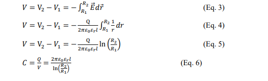
With the potential difference V. In this analysis, equations (Eq. 1) to (Eq. 4) are used to calculate capacitance in planar capacitors [2]. The equations explain how geometric choices and material characteristics influence capacitance values, emphasizing the crucial role geometry and material characteristics play.
Consequently, we find an expression similar to that of the planar capacitor: 2πR1: the perimeter of a cylindrical conductor 1: the length of the cylindrical capacitor 2rl the surface of the electrodes R2 − R1: the thickness of the dielectric of the cylindrical capacitor This equation of capacitance can then be used for a planar capacitor:

The profound understanding of geometric and material influences in capacitance emphasizes the critical role these elements play, setting the stage to investigate and address edge effects through the strategic utilization of circular electrodes in planar capacitors [2,3].
Significance of Circular Electrodes in Edge Effect Mitigation
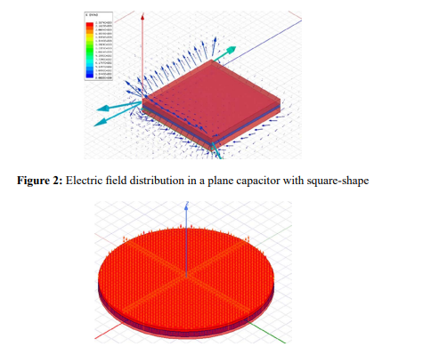
The choice of electrode shape significantly influences edge effects in planar capacitors. While the capacitor's capacitance is primar¬ily influenced by its surface area, the selection of electrode geometry remains crucial in minimizing edge phenomena. Based on the recommendation in, circular electrodes were preferred over rectangular or triangular electrodes [4]. A comprehensive simulation study was conducted to observe the divergence of electric fields at angles, as vividly illustrated in Figures 2 and 3.
As a function of the angle θ and distance r to the point considered, the potential can be calculated for any point in space near the electrode contour as shown in Figure 7.
This strategic approach acknowledges the inherent influence of surface area on capacitance while recognizing the nuanced impact of electrode geometry on edge effects. Circular electrodes are beneficial in promoting a more uniform electric field, which reduces edge effects effectively. Through this exploration, we enhance our understanding of the intricate interplay between surface considerations, geometric choices, and capacitor performance.
Edge Effects in Planar Capacitors
The electric potential of a generalized planar capacitor with parallel electrodes can be seen in Figure 4. In the diagram above, electrodes 1 and 2 are connected to ground and have a 5V potential, respectively.
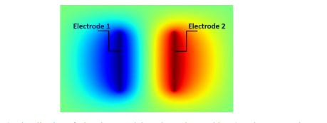
Figure 4: Visualization of Electric Potential at Electrode Level in a 2D Planar Capacitor
For an electrode surface S enclosing an inward-facing charge Qin within a volume V, Green's divergence theorem (Ostrogradsky) is utilized to derive Maxwell-Gauss equations in the air:
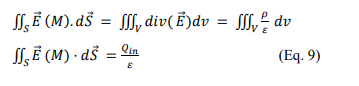
Here, ρ represents the volumetric charge density.
Divergent Electric Fields and Edge Effects
Divergent electric fields are observed outside the electrodes, producing edge effects, as depicted in Figure 5.
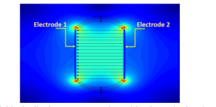
Figure 5: Electric Field Distribution Between and Outside Electrodes in a 2D Planar Capacitor
In Figure 5, arrow indicators illustrate electric field lines perpendicular to the electrodes, diverging at the electrode ends where a concentrated charge is located.
Evaluating External Field and Potential
To assess the field and potential outside the electrodes, a symmetrical charge distribution within a planar capacitor is considered, as shown in Figure 6.
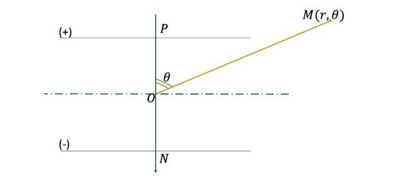
Figure 6: Equivalent 2D Approximation Scheme
The potential of the dipole NP is calculated as follows:

As a function of the angle θ and distance r to the point considered, the potential can be calculated for any point in space near the electrode contour as shown in Figure
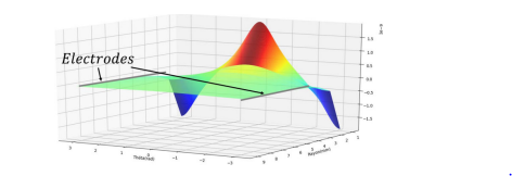
Figure 7: Plot of Electric Potential at Component Edges with Matlab
This section establishes an understanding of edge effects and the corresponding electric fields and potentials in planar capacitors.
Numerical Simulations and Experimental Performance
Capacitance and Field Distribution Analysis
At this crucial stage, we focus primarily on optimizing the dielectric's performance and preventing air ionization around the component, thereby minimizing edge effects and preventing premature breakdown. Figure 6 visually represents the electric potential plotted against the polar coordinates of point M in space, providing a comprehensive overview across all angles and radius values.
Figure 8 further elucidates these observations, indicating a substantial decrease in electric potential beyond 2 mm and its complete nullification after reaching 6 mm. This graphical representation emphasizes the effective management of electric potential at the component's edges, underscoring the modeling's significance in mitigating undesirable edge effects and upholding the component's structural integrity.
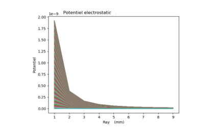
Figure 8. Electric Potential Tracing at the Component Edges
Empirical data align with these findings, where a dielectric with a 13 mm diameter recorded a capacitance of 76.5 pF, accompanied by an intense electric field around the electrodes and a breakdown voltage of 35 kV. Addressing these concerns led to an optimized breakdown voltage of 38 kV and an increased capacitance of 80.9 pF, seamlessly aligning with the governing equations (Equations 12 and 13).

The dielectric constant plays a crucial role in minimizing electric field divergence, which in turn enhances dielectric rigidity. By integrating both theoretical modeling and empirical validation, this comprehensive analysis highlights the proposed model's value in understanding and optimizing electronic component behavior. Specifically, it demonstrates the model's effectiveness in managing electric potential and mitigating edge effects, showcasing its practical application to improving component performance. B. Numerical Simulations with Maxwell 3D HFSS simulations were conducted to evaluate the capacitance variation with frequency and determine the component's resonance frequency. The simulations were performed with a perfect electrical conductor to force a perpendicular electric field at the electrode level, and a "Wave Port" excitation was defined at the ports to indicate the areas where energy enters and exits the conductive system, as shown in Figure 9. This approach allowed

Figure 9: 3D Modeling of the Prototype with a Margin
To evaluate the electric field distribution in the proposed model, numerical simulations using Maxwell 3D were conducted. The electrodes maintained consistent dimensions (13mm diameter with 15 µm thickness) to retain a consistent capacitance range. The ceramic layer remained 1mm thick. Two ceramic radii were examined: 13mm for a capacitor with metalized surfaces and 15mm for the same configuration with a 2mm margin (value for a comprehensive evaluation of the component's behavior, enabling the optimization of its performance by managing electric potential and effectively mitigating edge effects. The simulations provided a detailed understanding of the electric field distribution and capacitance variation with frequency, demonstrating the practical application of this approach in enhancing component performance.
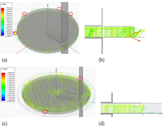
Figure 10: 3D Modeling of the Capacitor in static conditions (a) Without margin and (c) with 2mm of margin and 2D Visualization of Edge Effects(b) Without margin and (d) with 2mm
determined from Figures 10 (a) and (c), respectively). These simulations provided electrostatic resolution of Maxwell's equations, enabling the evaluation of capacitance and visualization of electric field distribution in both cases [6,7]. Figure 10 provides a detailed view of 3D capacitor modeling, presenting the scenario with a margin in static conditions and delivering a 2D visualization of edge effects.
In this configuration, the measured capacitance was 76.5 pF. An intensified electric field was observed around the electrodes and their proximity, which resulted in breakdown voltages of 35 kV. Design failure points were clearly highlighted in red, indicating areas of heightened concern (see Figure 10 (b)). In this study, the well-calculated margin to avoid air ionization and breakdown with edge effect plays an essential role in shaping field distribution, which affects planar capacitor operational efficiency and safety margins, and sheds light on critical design and optimization considerations for practical electronic applications [8,9].
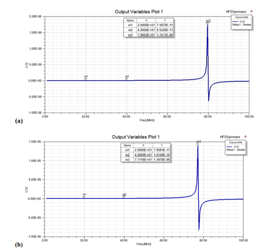
Figure 11: Capacitance Variation with Frequency in the Range [1 MHz, 100 MHz] (HFSS simulations): (a) model without a margin,
(b) model with a margin
In Figure 11, the capacitance variation with frequency is presented through HFSS simulations, providing crucial insights into the performance of the capacitor models under different conditions. Specifically, Figure 11 (a) illustrates the behavior of the model without a margin, showcasing a capacitance of 75.9 pF at 20 MHz and 95.2 pF at 40 MHz, with a resonance frequency estimated at 79 MHz. On the other hand, Figure 11 (b) depicts the model with a margin, exhibiting a capacitance of 79.5 pF at 20 MHz and 101.4 pF at 40 MHz, with a resonance frequency estimated at 77.1 MHz.
To understand the impact of the margin on capacitance and resonance frequency, these figures illustrate how capacitors react to varying frequencies. As we delve into the experimental performance of the prototypes in the subsequent sections, the insights gained from these simulations will be fundamental for interpreting and correlating the numerical and experimental findings [8,9].
Experimental Performance
The proposed capacitor prototype features a 1 mm thick B-phase wafer with circular electrodes and silver connections on both sides, manufactured through the doctor blade technique with a 2 mm margin (see Figure 12). Two capacitor models were crafted, one lacking a margin and the other incorporating a 2 mm margin [8-10].
Experimental Performance
The proposed capacitor prototype features a 1 mm thick B-phase wafer with circular electrodes and silver connections on both sides, manufactured through the doctor blade technique with a 2 mm margin (see Figure 12). Two capacitor models were crafted, one lacking a margin and the other incorporating a 2 mm margin [8-10].

Figure 12: The realized capacitor with a 2mm margin
At 1MHz, the margin-less model had 76 pF capacitance and the margin-containing model had 79 pF capacitance. This capacitance increase is attributed to the ceramic's higher relative permittivity (€r = 18) compared to air, aligning with numerical predictions. Losses remained minimal at 0.01% for both models.
Experimental assessment of DC breakdown voltage revealed notable findings. The margin-less model experienced a superficial breakdown at 19.3 kV in Galden (an insulating liquid that prevents any kind of external or surface breakdown), signifying a surface breakdown in the liquid with a recorded voltage of 20 kV. Conversely, the margin-inclusive model exhibited breakdown at 40 kV, indicating liquid breakdown and suggesting the margin's efficacy in preventing air ionization. The results underscore the importance of a margin exceeding a 2 mm radius for enhanced breakdown voltage.
In subsequent frequency domain measurements, the margin-inclusive capacitor's breakdown voltage was 1.6 kV at 50 MHz and the quality factor was 350. A discernible 0.2 kV increment in breakdown voltage, compared to the margin-less model, reaffirms the reduction of edge effects and an improved service voltage. The observed external breakdown, indicative of air ionization, underscores the imperative to extend the margin beyond a 2 mm radius.
Finally, incorporating a margin enhances the capacitor's voltage withstand capacity significantly. The proposed prototype with a margin advances these findings, presenting avenues for further enhancement.
Conclusions
The results of our study provide accurate calculations and estimations of the limits of electric fields and how they diverge. This understanding is pivotal for the optimal utilization of the dielectric material, encouraging the exploitation of its true dielectric strength. The primary objective is to mitigate the risk of premature electrical breakdown in components, particularly capacitors.
These insights hold significant implications for the development of a new generation of adjustable capacitors tailored for applications in Magnetic Resonance Imaging (MRI). Our approach sets the stage for designing more efficient components that meet the specific requirements of advanced technologies by combining precise predictions of electric fields with rigorous calculations and estimations. There are promising prospects for continued innovation in MRI capacitors as a result of these findings.
References
- Jebri, Z. (2019). Développement d'un nouveau type de condensateur ajustable amagnétique RF haute tension pour l'IRM. Ph.D. Thesis, University of Bordeaux.
- Vendik, O. G., Zubko, S. P., & Nikol’Skii, M. A. (1999). Modeling and calculation of the capacitance of a planar capacitor containing a ferroelectric thin film. Technical Physics, 44, 349-355.
- Chen, X., Zhang, Z., Yu, S., & Zsurzsan, T. G. (2019, November). Fringing effect analysis of parallel plate capacitors for capacitive power transfer application. In 2019 IEEE 4th International Future Energy Electronics Conference (IFEEC) (pp. 1-5). IEEE.
- Jebri, Z. (2019). Développement d’un nouveau type de condensateur ajustable amagnétique RF haute tension pour l’IRM. Université de Bordeaux. Français. HAL Id: tel-03024734.
- Bradley, M. P. (2004). Edge Effects in the Parallel Plate Capacitor: The Maxwell Transformation and the Rogowski Profile. EP464, Fall.
- Bueno Barrachina, J. M., Cañas Peñuelas, C. S., & Catalán Izquierdo, S. (2012). FEM edge effect and capacitance evaluation on cylindrical capacitors. Journal of Energy and Power Engineering, 6(12), 2063-2069.
- Jebri, Z., Majek, I. B., Delafosse, C., Pasquet, C., & Ousten, Y. (2018, May). A new non-magnetic trimmer for the magnetic resonance imaging system. In 2018 7th International Conference on Modern Circuits and Systems Technologies (MOCAST) (pp. 1-5). IEEE.
- Jebri, Z., Bord Majek, I., Delafosse, C., Pasquet, C., Ousjebriten, Y. (2018). Electrical modeling approach and manufacturing of a new adjustable capacitor for medical applications. In: 2018 7th Electronic System-Integration Technology Conference (ESTC), Dresden, Germany.
- Jebri, Z., Bord-Majek, I., Bardet, M., & Ousten, Y. (2023). FEM simulation-based development of a new tunable non-magnetic RF high voltage capacitor for the new generation of MRI. The Journal of Engineering, 2023(1), e12204.
- Jebri, Z., Taleb Ali, M., & Bord Majek, I. (2023). Investigating the effects of uniaxial pressure on thpreparation of MgTiO3–CaTiO3 ceramic capacitors for MRI systems. The Journal of Engineering, 2023(9), e12300.