
Journal of Electrical Electronics Engineering(JEEE)
ISSN: 2834-4928 | DOI: 10.33140/JEEE
Impact Factor: 1.2

Research Article - (2026) Volume 5, Issue 2
Insert Molding for Manufacturing Metal/Amorphous Polymer Jointed Parts Using Heat & Cool Injection Molding
Received Date: Feb 26, 2026 / Accepted Date: Mar 16, 2026 / Published Date: Mar 23, 2026
Copyright: ©2026 Goro Inoue, et al. This is an open-access article distributed under the terms of the Creative Commons Attribution License, which permits unrestricted use, distribution, and reproduction in any medium, provided the original author and source are credited.
Citation: Inoue, G., Kimura, K., Misumi, M. (2026). Insert Molding for Manufacturing Metal/Amorphous Polymer Jointed Parts Using Heat & Cool Injection Molding. J Electrical Electron Eng, 5(2), 01-06.
Abstract
The insert injection molding for manufacturing AL/amorphous polymer jointed parts using H&C injection molding was studied. Different from crystalline polymers such as PP, PPS, PA6, amorphous polymers couldn’t reach high bonding strength at the constant mold temperature condition. By using H&C injection molding method, it was confirmed that even with amorphous polymers, the lap-shear strength increased and the polymer entered sufficiently the micropores on the surface treated AL, as well as crystalline polymers.
Keywords
Insert Molding, Joining Different Materials, Amorphous Polymer, Heat & Cool Injection MoldingIntroduction
In recent years, technologies for joining different materials, such as metals and polymers, are actively being developed because the parts obtained in this way are excellent ones having conflicting properties such as strength and lightness, permeability and shielding of electromagnetic wave, insulation and dissipation of heat, and conductivity and insulation of electricity [1,2].
Among the joining techniques, the conventional joining method using an adhesive takes time to fix the adherend and harden the adhesive. In order to solve this problem, methods have recently been developed in which wet etching or laser treatment is used to create micropores on the surface of the metal, and the polymer is directly bonded to these pores through insert injection molding for thermoplastics. In that process, when a metal member that was surface treated is inserted into an injection molding mold and a resin is injected, the molten resin that has entered the micropores solidifies and can be jointed mechanically [3-5]. So far, many test results have been reported such as the combination of aluminum (hereinafter referred to as AL) and polyphenylene sulfide (as PPS), polybutylene terephthalate (as PBT), polyamide 6 (as PA6), and so on [3].
It is, however, possible to show sufficient bonding strength of the metal and resin composite in the case that resins are crystalline ones, and in the case of amorphous resins, it is difficult to reach high bonding strength. In this study, test results of the insert injection molding for manufacturing AL/amorphous polymer jointed parts using.
“Heat & Cool injection molding”, injection molding process under the mold temperature rapidly changing during injection, are reported.
Experimental details
Materials
Metals
An AL plate (thickness: 2.0 mm) of A5052 was cut into lengths of 45 mm and 18 mm wide for use as a specimen.
Polymers
As amorphous polymers, Acrylonitrile-butadiene-styrene copoly- mer (as ABS) (GA704 manufactured by Nippon A&L Inc., glass transition temperature: 105 °C), Polycarbonate (as PC) (Panlite L1225L manufactured by Teijin Limited, Tg: 146 °C), Polymethyl methacrylate (as PMMA) (Acrypet IRD30 by Mitsubishi Rayon Co., Ltd., Tg: 101 °C) Crystalline polymers, for comparison with amorphous ones, were also used such as Polypropylene (as PP) (Prime polypro V7100 manufactured by Prime Polymer Co., Ltd.), PPS (Susteel SGX-120by Tosoh Corporation,) and PA6 (Amilan CM-1011G30 by Toray Industries, Inc.).
Equipment
Injection Molding Machine
The injection molding machine, J85AD, manufactured by Japan Steel Works, Ltd., is used to create the test specimen, as shown Figure 1, which shape is specified in ISO19095-2, 4.2 as overlapped test specimen.
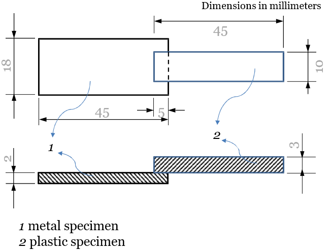
Figure 1: Shape and Dimensions of Overlapped Test Specimen
Temperature Controller for the Mold
Temperature control was performed by connecting a mold temperature controller (ATT H2 manufactured by Single Tempereriertechnck) to the mold for rapidly changing its temperature in Heat & Cool (hereinafter referred to as H&C) injection molding test.
Test Method
Surface Treatment of AL
AL specimen was etched with an acid-based etching agent (sulfuric acid: 8.2wt% ferric chloride: 7.8wt% (Fe3+: 2.7wt%), cupric chloride: 0.4wt% by mass (Cu2+: 0.2wt%), ion-exchanged water: remainder) at 30 °C by immersing it for 80 second. Next, ultrasonic cleaning (in water, 1 minute) was performed under running water in order to remove smut. After drying it, the surface treated specimen was obtained.
Injection Molding
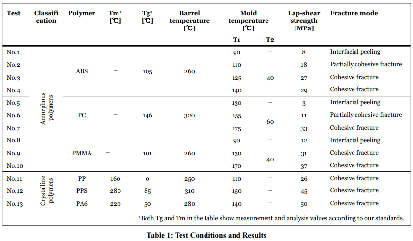
After the surface treated specimens was inserted in the mold, the injection molding was performed at the conditions shown in Table 1, and the test specimen was obtained.
In each test, the operation conditions of the injection molding machine such as its barrel temperature, injection speed, packing pressure and packing time were fixed, although those were adjusted according to the polymer, but only the mold temperature was changed in H&C injection molding test.
Incidentally, in this paper, injection molding at a constant mold temperature shall be called "normal injection molding".
Tensile Lap-Shear Strength Measurement
Tensile lap-shear strength measurement for evaluating bonding strength of AL and polymers, was performed in accordance with the method described in ISO 19095-3, 5.2.
A retainer with test specimen was attached to a tensile tester (model 1323, manufactured by Aikoh Engineering Co., Ltd.) and tensile test proceeded under conditions of a chuck distance of 60 mm and a tensile speed of 10 mm / min at room temperature (23 ° C). The lap-shear strength (MPa) was calculated by dividing the breaking load (N) obtained from the measurement by the area(50mm2) of the AL and polymer joint section.
Results and Discussion
Normal Injection Molding for Amorphous Polymers
The experimental conditions shown in Table 1 and their results will be described below. First, in Test No. 1, molding was performed at the constant mold temperature,90 ° C, lower than Tg of ABS so that it could be sufficiently solidified and taken out from the mold and also make it as fluid as possible. As a result, the lap-shear strength was 8 MPa and the failure mode of the bonding interface was interfacial delamination.
In order to investigate the state of bonding, the fractured surface structure in the interfacial area of AL -ABS jointed test specimen was observed. The electron micrographs ((a) magnification 500 times, (b) magnification 3000 times) were shown in Figure 2. As can be seen in those, there were many gaps between AL and ABS in the bonding interface obtained in No. 1, about 2μm gap in the large part, indicating that ABS could not sufficiently enter the micropores on the AL.
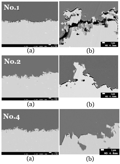
Figure 2: Electron Micrographs of AL (Lower Side)/ABS (Upper Side) the Fractured Surface Around its Bonding Interface ((a) Magnification 500 times, (b) Magnification 3000 times). No.1, No.2 and No.4 Indicate the Test Numbers in Table 1
As amorphous polymers other than ABS, PC and PMMA were also tested at a mold condition shown in No.5 and No.8 respectively, where the mold temperature was set to a temperature lower than Tg of each polymer. Again, both had low strength and interfacial peeling.
Normal Injection Molding for Crystalline Polymers
For comparison, three kinds of crystalline polymers were tested as shown in Table.1, No.11, No.12 and No.13. In those, the mold temperatures were set to a value higher than Tg and lower than the melting point (hereinafter referred to as Tm) to solidify. As a result, different from the amorphous polymers, all of them had high strength and destruction occurred in the polymer part. And in case of PP, as shown in Figure 3, sufficient entry into the bottom of micropores and almost no gaps were observed at the bonding interface.
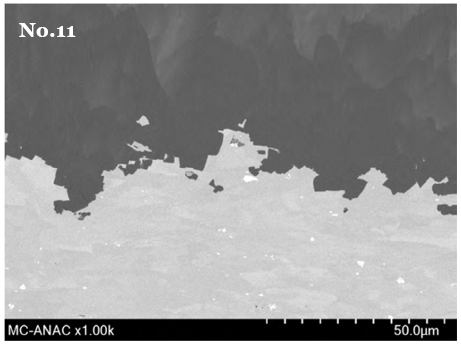
Figure 3: Electron Micrographs of AL (lower side)/PP (Upper Side) the Fractured Surface Around its Bonding Interface. No.11 Indicate the Test Numbers in Table 1
H&C Injection Molding for Amorphous Polymers
To improve insufficient joint conditions in amorphous polymers, H&C injection molding test had performed. From the above results, the authors presumed that this was because the flow rate of the amorphous resin significantly decreased due to rapid cooling below Tg. Therefore, the test was conducted by setting the temperature of the mold above Tg (referred to as T1) until the completion of injection, and then lowering the temperature below Tg (referred to as T2) after completion of injection. A schematic diagram of this temperature change in case of ABS was shown in Figure 4, (a) for the constant mold temperature, such as test No.1, (b) for the H&C test such as test from No.2 to No.4. These three tests, T1 was set to 110°C(No.2), 125°C(No.3) and 140°C(No.4), respectively, and T2 was set to 40°C for all of them. As a result, the joint strength was 18 MPa (No. 2), 27 MPa (No. 3) and 29 MPa (No. 4), respectively, and from this, it was found that the strength increased with the increase of T1. Similarly, the failure mode of the joint interface also changed with the increase of T1, with partial material failure in No.2 and complete material failure in No.3 and No.4. Moreover, from the observation results of the fractured surface structure of the No.2 and No.4 in Figure 2, it was found that the gaps between AL and ABS decreased as T1 increased and almost disappeared in No.4.
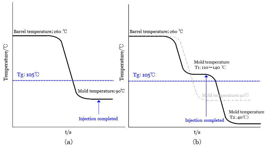
Figure 4: Schematic Diagram Expressing Changes in Temperature Over Time During the ABS Polymer Injection Molding Process. (a) Normal Injection Molding and (b) H&C Injection Molding
Similar tests were performed with other amorphous polymers. H&C injection molding test conditions and results were also shown in Table1, No.6&7 for PC, No.8&9 for PMMA. As in the case of ABS, the joint strength increased with increasing T1 and the failure mode were material failure for both polymers.
Conclusion
The insert injection molding for manufacturing AL/amorphous polymer jointed parts using H&C injection molding was studied. Different from crystalline polymers such as PP, PPS, PA6, amorphous polymers couldn’t reach high bonding strength at the constant mold temperature condition. From the results of structural observation, it was found that the polymer could not sufficiently enter the micropores. It is presumed that the cause was that the mold temperature was rapidly cooled below Tg. In order to solve this problem, H&C injection molding tests were carried out under the conditions that the temperature of the mold above Tg until the completion of injection, and then lowering the temperature below Tg after completion of injection. As a result, it was confirmed that even with amorphous polymers, the lap-shear strength increased and the polymer entered sufficiently the micropores on the surface treated AL, as well as crystalline polymers.
References
- Takenaka, K., Machida, R., Bono, T., Jinda, A., Toko, S., Uchida, G., & Setsuhara, Y. (2022). Development of a non- thermal atmospheric pressure plasma-assisted technology for the direct joining of metals with dissimilar materials. Journal of Manufacturing Processes, 75, 664-669.
- Wang, H., Yan, P., Ding, X., & Guan, Y. (2022). Enhanced laser direct joining of continuous carbon fiber reinforced polyetheretherketone and titanium alloy with controllable mechanical interlocks. Journal of Manufacturing Processes, 86, 56-65.
- Chen, W., Kimura, F., & Kajihara, Y. (2023). Effect of nanostructured zinc coating on high joining strength of polymer/galvanized high-strength steel composite via injection molding. Journal of Manufacturing Processes, 85, 295-305.
- Wang, S., Kimura, F., Zhao, S., Yamaguchi, E., Ito, Y., &Kajihara, Y. (2021). Influence of fluidity improver on metal-polymer direct joining via injection molding. Precision Engineering, 72, 620-626.
- Zhao, S., Kimura, F., Wang, S., & Kajihara, Y. (2021). Chemical interaction at the interface of metal–plastic direct joints fabricated via injection molded direct joining. Applied Surface Science, 540, 148339.