

Advances in Bioengineering and Biomedical Science Research(ABBSR)
ISSN: 2640-4133 | DOI: 10.33140/ABBSR
Impact Factor: 1.7

Research Article - (2024) Volume 7, Issue 1
Innovative Test Bench for RF and High-Voltage Component Characterization for MRI Applications: A Comprehensive Review
2LAPER, Faculty of Sciences of Tunis, El Manar University, Tunisia
3I2M Laboratory, CNRS UMR 5295, U. Bordeaux,Talence, France
4LMAI-ENIT, Tunis El Manar University, Tunisia
Received Date: Jan 09, 2024 / Accepted Date: Feb 05, 2024 / Published Date: Feb 12, 2024
Copyright: ©Ã?©2024 Zaineb Jebri, et al. This is an open-access article distributed under the terms of the Creative Commons Attribution License, which permits unrestricted use, distribution, and reproduction in any medium, provided the original author and source are credited.
Citation: JEBRI, Z., Taleb Ali, M., Malek Belouda, M., Mami, A. (2024). Innovative Test Bench for RF and High-Voltage Component Characterization for MRI Applications: A Comprehensive Review. Adv Bioeng Biomed Sci Res, 7(1), 1-5.
Abstract
This scientific paper presents a detailed exploration of the electrical characterization of commercially available trimmers, conducted in collaboration with Siemens Medical. The study encompasses the establishment of a specialized measurement bench for impulse mode electrical tests, involving the adaptation of the signal generator with an adjustable supercapacitor and variable inductance. For precise measurements, a carefully designed filtering system prevents voltage overshoots.
Given the critical sensitivity of voltage and frequency measurements for passive components in RF and high-voltage applications, the methodology is further refined to achieve optimal compromises across various parameters. The primary objective remains the determination of the voltage across the evaluated capacitor using the proportionality coefficient α, essential for accurate trimmer characterizations.
In this paper, useful insights are provided into the electrical characterization of trimmers, as well as a refined methodology designed for RF and high-voltage applications. The findings presented herein enhance our understanding of trimmer behavior, offering potential implications for improved component selection and performance in a range of electrical systems.
Introduction
The ever-evolving landscape of electronic applications, particularly in fields such as radio frequency (RF) and high-voltage applications, demands a meticulous understanding of the electrical characteristics of crucial components. This paper embarks on a scientific exploration into the electrical characterizations of commercially available trimmers, integral components in diverse technological applications. Conducted in collaboration with Siemens Helathineers©, this study addresses the critical need for precision in voltage and frequency measurements, especially for passive components operating in RF and high-voltage environments [1,2].
As technological advancements continue to push the boundaries of electronic applications, the demand for optimized performance and reliability becomes increasingly paramount. Trimmers, as key elements in various circuits, play a pivotal role in achieving desired electrical characteristics [3,4]. However, their behavior in specialized domains, such as RF and high-voltage applications, presents unique challenges that necessitate a thorough investigation.
To address these challenges, a dedicated measurement bench has been established, allowing for impulse mode electrical tests with a particular focus on adapting signal generators for accurate measurements. The introduction of adjustable supercapacitors and variable inductances, coupled with a sophisticated filtering system, aims to achieve optimal compromises across multiple parameters. This tailored approach becomes indispensable to ensure not only the precise characterization of trimmers but also their effective performance within desired operating domains [5].
This paper unfolds the intricate methodologies employed in establishing the measurement bench and addresses the sensitivity of voltage and frequency measurements [6,7]. By delving into the nuances of trimmer behavior, this study not only enhances our understanding of these components but also paves the way for improved selection and performance in advanced electronic systems. In navigating through the challenges and solutions encountered, we seek to contribute valuable insights to the broader scientific community and propel advancements in the realm of electrical characterization for RF and high-voltage applications [8].
Theoretical Framework for RF and High-Voltage Measurements
Characteristics of RF Environments
In passive components, RF measurements affect their electrical characteristics. Indeed, the skin effect, represented by the following equation, illustrates the concentration of current towards the outer surface of conductors.
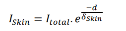
where ISkin is the skin effect current, Itotal is the total current, d is the depth into the conductor, and δ skin is the skin depth. Additionally, the propagation of electromagnetic waves in RF environments can be characterized by the following equation for the wavelength (λ):

where c is the speed of light and f is the frequency.
Challenges and Considerations in High-Voltage Environ-ments
High-voltage measurements introduce challenges that require careful consideration for both safety and accuracy. The breakdown voltage (Vbreakdown) of insulating materials can be defined as the point at which insulators cease to resist the applied voltage. This parameter is critical to prevent insulation failure.
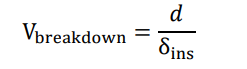
where d is the distance between conductors and δins is the insulation thickness.
Passive Component Behavior in RF and High-Voltage Environments
Passive components, particularly trimmers, are influenced by their internal parameters: capacitance (C), inductance (L), and resistance (R). The resonant frequency (fres) of a circuit, where C and L are in series, is given by.
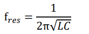
In high-voltage scenarios, the insulation resistance (Rins) is crucial and can be represented as:
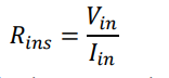
where Vins is the applied voltage across the insulation and Iins is the leakage current.
Implications for Measurements
The challenges posed by RF and high-voltage environments have direct implications for electrical measurements. Precise voltage measurements (Vmeasured) demand consideration of impedance matching, shielding effectiveness (SE), and minimizing parasiti ceffects.
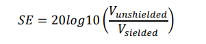
The frequency-dependent characteristics of passive components necessitate a careful approach to capture accurate responses in RF applications.
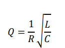
Additionally, the potential for corona discharge and insulation breakdown in high-voltage scenarios requires robust measurement setups to ensure safety and reliability.
In summary, these equations encapsulate the theoretical foundations for RF and high-voltage measurements, laying the groundwork for devising effective measurement strategies. Next, we will examine the solutions implemented to address these challenges and the practical tests conducted to validate the measurement circuit adaptation.
Electrical Characterization Test Bench Setup
To conduct thorough electrical characterizations of the selected trimmers, a dedicated measurement bench was established in collaboration with Siemens Medical, a renowned MRI systems manufacturer. This section outlines the setup and methodology employed for pulse regime electrical tests.
Presentation of the Electrical Characterization Bench
In this test bench, capacitors are thoroughly evaluated and characterised, especially those intended for use in RF and high-voltage applications. Its configuration and equipment are strategically chosen to ensure precise measurements and reliable assessments. The schematic overview of the characterization bench used for pulse regime electrical tests is illustrated in Figure 1.
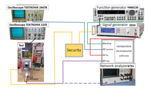
Figure 1: Schematic Overview of the Electrical Characterization Bench
The equipment ensemble comprises a robust RF power amplifier, essential oscilloscopes, a network analyzer, and a high-frequency (HF) generator. Each device plays a distinct role in the testing process, contributing to the overall accuracy and reliability of the results. Specifically, the RF power amplifier is a crucial component responsible for amplifying the product of input voltage (Ue ) and input current (Ie ) with a gain corresponding to Ps /Pe . For RF systems, a characteristic impedance of 50Ω is standard. A comprehensive understanding of the amplifier'sbehavior is essential, particularly concerning its saturation point and non-linear characteristics, as these factors significantly influence subsequent measurements, ensuring the scientific rigor of the paper.
Test Methodology
The JIG, or test box, incorporates key elements such as an adjustable supercapacitor (Cvar) and a variable inductor (Lvar), as shown in Figure 1. These components, calibrated across ten settings, facilitate the adaptation of the JIG to the desired frequency, crucial for minimizing reflections and ensuring accurate measurements. Their values ranged from 1 to 100 F and 2 to 15 nH, respectively [5-7].
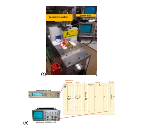
Figure 2: (a) Test Box and (b) Equivalent Schema The chosen resistance is R = R2 = R1=50 kΩ.
Central to the system is the adaptation network, where the supercapacitor and inductor are meticulously adjusted. This adaptive process is critical to achieving resonance at the desired frequency, thereby minimizing reflections and enhancing the overall performance of the test bench. A filtering system (composed of the liaison capacitance Cliaison and resistances R1, R2, and R3) was included in the measurement box, as shown in Figure 2 (b). This system, positioned alongside the capacitor (cf. Figure 2 (a)), prevented exceeding the maximum voltage level supported by the oscilloscope (cf. Figure 2 (b)) [9].
Voltage Measurement and Characterization
The measured Qp corresponds to the quality factor of a parallel RLC circuit, as illustrated in Figure 3.
The primary objective is to measure the voltage (Ucut) across the capacitor under characterization [10]. This voltage is crucial for understanding the behavior of the trimmers, the evaluation of breakdown and the determination of the service voltage of the tested capacitor become integral aspects of the testing process, ensuring the reliability and safety of the components. This is achieved using the proportionality coefficient α between the measured voltage (Ucut) and the voltage displayed on the oscilloscope (Umon) :
Ucut = α Umon
The coefficient α is a complex expression, expressed as:
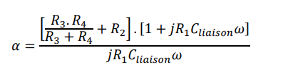
This coefficient is used to establish the relationship between the measured voltage (Ucut) and the voltage displayed on the oscilloscope (Umon). It takes into account various factors in the circuit, including resistance (R2, R3, and R4) as well as the frequency (ω) and the capacitance (Cliaison) in the circuit.
Quality Factor Determination
A network analyzer 8753 is used to characterize the behavior of the circuit by measuring S-parameters, which gives insight into the parameter determination process. Subsequently, the quality factor (Qp) is assessed at the corresponding frequency, offering crucial information about the efficiency and resonance characteristics of the circuit (by calculating losses) [11,12]. The quality factor is crucial in understanding the efficiency and resonant characteristics of the circuit [13].
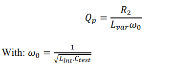
The measured Qp corresponds to the quality factor of a parallel RLC circuit, as illustrated in Figure 3.
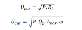
The given values, such as: Eg= 87V and P = 0.02W, are used in the calculations.
Experimental Results and Analysis
In the context of RF applications and adaptation requirements, the voltage across the ceramic capacitor, denoted as Ucut, manifests as a rectangular waveform with a duty cycle of 5% [14]. This waveform is modulated by the frequency corresponding to the chosen quality factor [15]. The measured characteristics of commercially available capacitors are succinctly presented in Table 1:
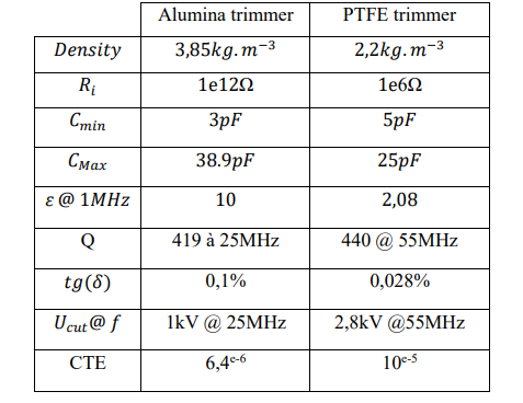
Table 1. Characterization table of purchased capacitors
Table 1 summarizes the comprehensive characterization of the selected capacitors. At the terminals of the ceramic capacitor, the recorded voltage, Ucut, stabilizes at 1024V.
To validate this outcome, a battery of ten capacitors (specifically referencing SGNMNC3306) underwent rigorous testing, affirming the saturation of this voltage around 1kV, with measurements ranging from 1019V to 1024V. The PTFE trimmers, sourced from the NMNT 23-6 reference, exhibit an almost identical quality factor of approximately 440 at a frequency of 55 MHz.
Under specific conditions, these experiments shed light on both capacitors' and trimmers' performance and limitations, thereby improving our understanding of their behavior in practical applications. Furthermore, a comparative analysis of measurements conducted by MRI designers reveals a commendable alignment of results, which confirms the consistent testing methodologies and compatibility with RF and HF environments. Such coherence strengthens the reliability of the obtained data and enhances confidence in the applicability of these components to MRI applications.
Conclusions
In summary, our endeavor to construct a sophisticated test bench for RF and high-voltage component characterization in MRI applications has yielded substantial insights. This scientific exploration, conducted in collaboration with Siemens Medical, delved into the electrical characterization of commercially available trimmers, employing a specialized measurement bench for impulse mode electrical tests. Our methodology, refined for precision in voltage and frequency measurements, aims at optimal compromises across various parameters, with a primary focus on determining the voltage across evaluated capacitors using the proportionality coefficient 
This paper contributes valuable insights into the electrical characterization of trimmers and introduces a refined methodology tailored for RF and high-voltage applications.
The intricate methodologies employed in establishing the measurement bench address the sensitivity of voltage and frequency measurements, providing a foundation for improved component selection and performance in advanced electronic systems. By navigating through encountered challenges and presenting effective solutions, we aim to propel advancements in the field of electrical characterization for RF and high-voltage applications. Theoretical frameworks for RF and high-voltage measurements were thoroughly discussed, covering the characteristics of RF environments and considerations in high-voltage environments. Equations encapsulating the theoretical foundations were presented, laying the groundwork for effective measurement strategies. Subsequently, the detailed description of our electrical characterization test bench setup, in collaboration with Siemens Medical, illustrated the strategic selection of equipment and configuration to ensure precise measurements and reliable assessments.
The experimental results and analysis provided comprehensive insights into the performance and limitations of capacitors and trimmers under specified conditions. The comparison of our data with measurements conducted by MRI designers showcased consistency, affirming the reliability of our testing methodologies in RF and HF environments. The alignment of results enhances confidence in the applicability of these components to MRI applications.
In conclusion, our research not only enhances our understanding of trimmer behavior but also offers practical solutions and data that can significantly contribute to advancements in the broader scientific community. The comprehensive nature of our study, from theoretical frameworks to experimental validations, positions our work as a valuable resource for researchers, designers, and manufacturers in the field of electronic applications for MRI
References
- Lee, T. H. (2004). Planar microwave engineering: a practical guide to theory, measurement, and circuits (Vol. 1). Cambridge university press.
- Sadiku, M. N. O. (2014). Elements of Electromagnetics. Chapters 10, p 443.
- Hoft, R. G., & Elmore, W. C. (1979). Physics of Conductors and Insulators. Chapter 4, p. 465.

- Jebri, Z., Majek, I. B., Delafosse, C., Pasquet, C., & Ousten, Y. (2018, May). A new non-magnetic trimmer for the magnetic resonance imaging system. In 2018 7th International Conference on Modern Circuits and Systems Technologies (MOCAST) (pp. 1-5). IEEE.
- Jebri, Z., Majek, I. B., Delafosse, C., & Ousten, Y. (2018, September). Electrical modeling approach and manufacturing of a new adjustable capacitor for medical applications. In 2018 7th Electronic System-Integration Technology Conference (ESTC) (pp. 1-5). IEEE.
- Jebri, Z., Bord-Majek, I., Bardet, M., & Ousten, Y. (2023). FEM simulation-based development of a new tunable non-magnetic RF high voltage capacitor for the new generation of MRI. The Journal of Engineering, 2023(1), e12204.
- Jebri, Z., Taleb Ali, M., & Bord Majek, I. (2023). Investigating the effects of uniaxial pressure on the preparation of MgTiO3–CaTiO3 ceramic capacitors for MRI systems. The Journal of Engineering, 2023(9), e12300.
- Paul, C. R. (2008). Introduction to Electromagnetic Compatibility. Chapters 2, p. 167.
- Balda, J. C. (2000). High Voltage Engineering: Fundamentals. Chapter 4, p. 364.
- Pozar, D. M. (2012). Microwave Engineering. Chapter 2, p. 182.
- Zucker, F. J. (2017). Corona Performance of High Voltage Transmission Lines. The book should provide detailed insights into corona discharge, Chapter 4, p. 224.
- Ludwig, R., & Bretchko, P. (2009). RF Circuit Design: Theory and Applications. Chapters 3, p. 201.
- Pozar, D. M. (2000). Microwave and RF design of wireless systems. John Wiley & Sons.
- Whitaker, J. C. (Ed.). (1996). The electronics handbook. Crc Press.