

Advances in Bioengineering and Biomedical Science Research(ABBSR)
ISSN: 2640-4133 | DOI: 10.33140/ABBSR

Impact Factor: 1.7

Research Article - (2024) Volume 7, Issue 1
Innovative Design and Optimization of Adjustable Capacitors for Radio-Frequency new MRI Systems
2I2M Laboratory, CNRS UMR 5218, U. Bordeaux,Talence, France
Received Date: Jan 09, 2024 / Accepted Date: Feb 05, 2024 / Published Date: Feb 27, 2024
Copyright: ©Â©2024 Zaineb JEBRI, et al. This is an open-access article distributed under the terms of the Creative Commons Attribution License, which permits unrestricted use, distribution, and reproduction in any medium, provided the original author and source are credited.
Citation: JEBRI, Z., Taleb Ali, M. (2024). Innovative Design and Optimization of Adjustable Capacitors for Radio-Frequency new MRI Systems. Adv Bioeng Biomed Sci Res, 7(1), 1-8.
Abstract
This review delineates significant strides in the evolution of adjustable capacitors tailored specifically for high- frequency Magnetic Resonance Imaging (MRI) applications. The research spans critical phases, meticulously detailing the adaptation of electrode shapes to attain versatile capacitance within a high-frequency spectrum. The prototype, a key focal point, showcases distinctive attributes, featuring silver-fixed and CuNiZn half-disc mobile plates mounted on a MgTiCa ceramic pellet. Comprehensive evaluation, incorporating simulation and measurement at 10MHz, illuminates the prototype's capacitance dynamics.
The optimization model scrutinizes pivotal parameters governing capacitor assembly, placing a specific emphasis on the profound influence of air gap thickness on rotor equilibrium. A granular analysis of the air gap's impact on capacitance and self-resonance frequency enriches the study, offering valuable insights into configurations optimized for high- frequency MRI applications. Validation of the prototype's electrical properties through the HP Agilent 4192A LF Impedance Analyzer establishes a robust correlation with simulation results, effectively aligning with stringent MRI system specifications. The intricate assembly process, inclusive of electrode optimization considering frequency nuances and the innovative use of silver glue, is meticulously expounded upon.
In-depth discussion encapsulates the rigorous validation of the development process, the stability exhibited by chosen materials across varying frequencies, and the nuanced influence of the air gap on capacitance. After concluding that the prototype meets specifications, the study charts a course for future research toward competitive trimmers for high- frequency MRIs.
What distinguishes this research is its meticulous exploration of electrode shapes, the unique composition of the prototype, and a comprehensive analysis of the intricate interplay between air gap variations and capacitor performance. This work is distinguished further by the inclusion of silver glue that enhances practical implementation.
Keywords
Adjustable Capacitor, New-Generation, Capacitance, Design, ESR, SRF
Introduction
In the dynamic landscape of Magnetic Resonance Imaging (MRI) technology, characterized by continuous evolution and innovation, the demand for specialized components has surged to meet the unique requirements of this field. Among these, adjustable capacitors emerge as pivotal contributors, playing a crucial role in optimizing Radio Frequency (RF) circuits in MRI applications. Precision and reliability stand as paramount considerations in this realm, particularly given the formidable standards set by 3 Tesla static magnetic fields and a resonance frequency of 128MHz.
This comprehensive review embarks on a meticulous exploration of a novel generation of adjustable capacitors expressly designed for high-frequency MRI systems. Recognizing the criticality of the manufacturing and validation stage, the study addresses the need for adaptive electrode shapes, ensuring variable capacitance within a specific range. The prototype, featuring silver-fixed and CuNiZn half-disc mobile plates mounted on a carefully engineered MgTiCa ceramic pellet, stands as the central focus of the investigation. Simulations and measurements conducted at 10MHz unravel the intricacies of capacitance variation, setting the foundation for further analysis.
Moving beyond the manufacturing stage, the review introduces an optimization model that accentuates the paramount importance of key parameters in assembling the main capacitor components—the stator and rotor. An insightful exploration into the impact of the air gap between the rotor and dielectric base on rotor equilibrium enhances our understanding of optimal design considerations. This meticulous analysis extends to the influence of the air gap on capacitance and self-resonance frequency, offering valuable insights for achieving a design that aligns seamlessly with the demanding specifications of high-frequency MRI.
Thorough scrutiny of the prototype's electrical properties, facilitated by advanced instrumentation, ensures alignment with stringent MRI system specifications. The final assembly process, elucidating electrode optimization considering frequency nuances and the innovative utilization of non-magnetic silver glue, is detailed for practical implementation.
As the discussion unfolds, the review critically examines the validation of the development process, underscores the stability of chosen materials across varying frequencies, and probes into the nuanced impact of the air gap on capacitance. Importantly, the study concludes by affirming the prototype's unwavering adherence to specifications, unveiling a promising avenue for future developments in competitive trimmers tailored specifically for high-frequency MRI applications. This research,

(a) (b) (c)
Figure 1: Plate location for (a) the minimum capacitance value, (b) an intermediate capacitance value and (c) the maximum capacitance value
rooted in the imperative of avoiding the excitation of magnetic metals during MRI operations, is positioned at the forefront of innovation within this intricate domain.
Capacitance Variation and Simulation Analysis
To optimize adjustable capacitors for MRI applications, this section emphasizes the critical aspect of achieving variable capacitance within a specified range (3 to 30 pF) based on MRI requirements. The electrode shape is meticulously adapted, with each electrode on both sides of the ceramic in the form of a half-disc. The prototype, characterized by a 30mm diameter, incorporates a 10° rotation of the mobile electrode, resulting in a 1.5 pF capacitance variation step. This deliberate design choice reduces the number of screw turns required for adjustment, enhancing ease and speed.
To validate the theoretical concepts, a trimmer prototype is manufactured, featuring a silver fixed electrode deposited via screen-printing on one side of the ceramic disc, along with a CuNiZn half disc serving as the mobile plate. The MgTiCa ceramic pellet, crafted with precision (1mm thickness, 30mm diameter, 3.15 g.cm-3 density), is fabricated using a dedicated mold for the shield (2mm of marge) [FEM].
Simulation and measurement activities are undertaken to scrutinize the adjustable capacitor's performance. Fig. 1(a), (b), and (c) visually represent the positions of the two electrodes corresponding to minimum, intermediate, and maximum capacitance values, offering a tangible insight into the dynamic behavior of the prototype.
Simulations and measurements at 10MHz further confirm the capacitor's adherence to specifications, displaying a minimal capacitance of 3.7pF (measurement) and 3.8pF (simulation) and a maximal capacitance of 30pF (measurement) and 33pF (simulation). These values align with the required 3 to 30 pF capacitance range for MRI applications, indicating promising results for the new prototype in comparison to existing components.
As a prelude to this detailed exploration, it is essential to acknowledge the broader significance of adjustable capacitors in MRI technology. These components not only serve as crucial elements within RF circuits but also stand as linchpins in ensuring precision, especially under the challenging conditions posed by 3 Tesla static magnetic fields and a resonance frequency of 128MHz. This section thus lays the foundation for a comprehensive understanding of the innovative strides undertaken in the subsequent stages of this research.
Optimization Model for Enhanced Performance
In advancing the capacitor's efficacy beyond the manufacturing stage, a comprehensive optimization model is introduced, underscoring the pivotal factors involved in assembling capacitor components, specifically the stator and rotor. A primary focus is dedicated to exploring the profound impact of air gap thickness on rotor equilibrium, a critical determinant of achieving peak performance. This optimization model presents a systematic approach, meticulously fine-tuning the capacitor's design to ensure steadfastness and efficacy in high-frequency MRI applications.
Within this contextual framework, the section intricately dissects the nuanced relationship between air gap thickness and

Figure 2: Capacitance variation versus the rotation angle at 10MHz (measurement and simulation)
rotor equilibrium. By delving into this parameter, the section provides profound insights into the meticulous adjustments that significantly influence the overall performance of an adjustable capacitor. The integration of theoretical models and numerical methods not only validates the optimization model but also establishes a robust foundation for achieving precise control over capacitance in real-world applications.
The exploration is further substantiated through a tangible application, where simulations and measurements are conducted on an adjustable capacitor. Fig. 2 visually encapsulates the variation in capacitance versus the rotation angle at 10MHz, showcasing the trimmer's real operating conditions in the air, mirroring the environment of MRI devices.
As depicted in Fig. 2 the measurements impeccably align with the simulation results. A minimal capacitance of 3.7pF (measurement) and 3.8pF (simulation) and a maximal capacitance of 30pF (measurement) and 33pF (simulation) is attained at 10MHz. A precise fine-tuning of 1.6pF is estimated through measurements, alongside estimations of breakdown voltage and self-resonance frequency. The ensuing discussion reveals a noteworthy accord between simulation and measurement results, affirming the prototype's adherence to the electrical
(a) (b)
(b)
Figure 3: (a) The sectional view of the new prototype and (b) the equivalent circuit
specifications required for MRI trimmers. Optimizing the adjustable capacitor's design addresses the profound influence of air gap thickness on rotor equilibrium for peak performance in MRI applications. It confirms detailed fine-tuning and adherence to stringent electrical specifications for MRI trimmers through tangible simulations and measurements.
Optimization of Air Gap
A critical factor in rotor equilibrium, the air gap is meticulously examined. The ceramic surface's flatness is highlighted as pivotal for maintaining rotor equilibrium and controlling air gap thickness effectively. In the maximum configuration, the equivalent capacitance (Ceq) is deduced from the combination of serial capacitances (CCeramic, CAir), as depicted in Fig. 3 (b). Then, the equivalent capacitance (Ceq) is determined by the formula

This expression signifies the combined effect of serial capacitors (CCeramic and CAir), where εr represents the relative permittivity, ε0 is the vacuum permittivity, S denotes the surface area, eAir stands for the air gap thickness, and e corresponds to the ceramic thickness. The derived equivalent capacitance serves as a comprehensive indicator of the capacitor's performance, accounting for the influences of both ceramic and air components.
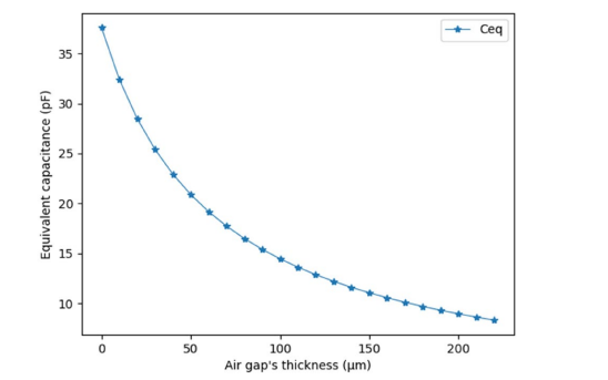
Figure 4: Capacitance versus the air gap
This conceptual framework provides a robust basis for calculating the impact of air gap thickness on capacitance. The ensuing exploration in Fig. 4 reveals the substantial influence of air capacitance on equivalent capacitance, underlining the necessity for a delicate balance in air gap thickness. Moreover, air gaps between the ceramic and mobile electrodes are shown to influence the self-resonance frequency (SRF). The SRF variation versus the air gap is meticulously tabulated in Table 1, elucidating the dynamic relationship between air gap thickness and self-resonance frequency.
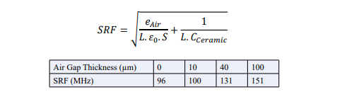
Table 1: Air gap influence on the self-resonance frequency
A meticulous air gap thickness of 40µm is highlighted, resulting in an air capacitance (CAir) of approximately 55pF. This configuration yields an equivalent capacitance (Ceq) of 27pF (<30pF) and an SRF of 131MHz (>128MHz). The interplay between these parameters underscores the importance of optimization in achieving the desired electrical properties for the prototype.
Electrical Property Validation
To corroborate the theoretical framework with practical measurements, electrical properties of the prototype are rigorously assessed. Employing the HP Agilent 4192A LF Impedance Analyzer, a signal generator, and an oscilloscope, the prototype undergoes scrutiny in the frequency range of [2Hz, 13MHz]. Table 2 succinctly summarizes the electrical properties, affirming the prototype's adherence to the required specifications for MRI systems.
|
Electrical Properties |
Value |
|
Minimum capacitance |
3pF |
|
Maximum capacitance |
26.9pF |
|
Breakdown voltage |
2.86 kV |
|
Resonance frequency |
131 MHz |
Table 2: Measurement of Electrical Properties of the Prototype
A notable alignment between measurement and simulation results is observed, bolstering confidence in the prototype's suitability for high-frequency MRI applications. The high-quality factor of approximately 500 at 60MHz and 395 at 95MHz further underscores the prototype's efficacy, validating its industrial readiness for MRI applications.
(a) (b)
(b)
Figure 5: (a) 3D and (b) real prototype design
The culmination of the optimization model is reflected in the final assembly of the designed parts (Fig. 5). Utilizing screws, clips, and other connections within a casing, the assembly ensures the minimization of magnetic interference. This optimization of the physical assembly complements the meticulous design considerations, enhancing the overall performance of the prototype in real-world MRI operating conditions.
Optimization of Electrodes
Delving into intricate details, this section meticulously addresses the optimization of electrodes, a critical component in achieving superior performance for high-frequency MRI applications. Operating within the constraints of frequency requirements, the recommended electrode thickness is emphasized to be at least three times (or five times, as per [16]) the skin depth. The selection of materials (silver for the fixed electrode and CuNiZn for the rotor) is justified based on their exceptional electrical conductivity and mechanical rigidity.
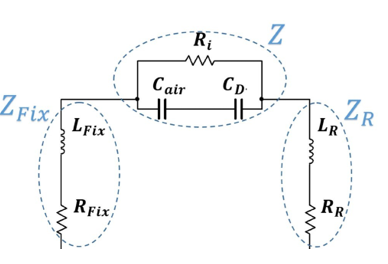
Figure 6: Equivalent circuit of a capacitor
To mitigate thickness and conductor losses, a strategic application of silver glue (He20) is employed, leading to a precise polymerization process at 150°C [19]. Fig. 6 illustrates the resulting improvement in the quality factor, estimated to be 30mOhm based on the PI topology. The integration of silver glue ensures connections are made without overflow and with a minimum of air bubbles, contributing to enhanced overall performance.
Equivalent Circuit of a Capacitor
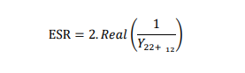
The Equivalent Series Resistance (ESR) represents the overall series resistance in a capacitor. The ESR is given by the formula, indicating that the optimization efforts not only address conductor losses but also notably enhance the quality factor, as highlighted in Fig. 6.
This practical implementation of these optimizations ensures that the designed capacitor not only meets theoretical expectations but excels in real-world applications, particularly in the demanding realm of high-frequency MRI systems. This section provides an exhaustive examination of the electrical properties of the prototype, validated through advanced instrumentation such as the HP Agilent 4192A LF Impedance Analyzer. The discussion encompasses practical aspects of assembly, including the optimization of electrodes with considerations for frequency and the innovative use of silver glue. Further detailing measurement techniques and practical insights gained during the electrode optimization process adds depth to the overall narrative. The transition after the section smoothly connects the electrode optimization discussion to the broader context of the study.
sides of the ceramic—proves pivotal. With a 30mm diameter, a meticulously calculated 10° rotation of the mobile electrode ensures a 1.5 pF capacitance variation step. This deliberate design choice significantly reduces the number of screw turns, streamlining adjustment for optimal efficiency.
To validate these theoretical concepts, a trimmer prototype was meticulously manufactured. The silver fixed electrode, expertly deposited via screen-printing, complements the CuNiZn half-disc mobile plate. The MgTiCa ceramic pellet, crafted with precision (1mm thickness, 30mm diameter, 3.15 g.cm-3 density), was meticulously formed through pressing and sintering processes, utilizing a dedicated mold for the shield (2mm width and 7mm height
Discussion on Development Process and Material Stability
For MRI applications, precision in achieving variable capacitance within the specified range (3 to 30 pF) is paramount, as indicated in Table I. The intricate adaptation of electrode shapes—featuring fixed and mobile half-disc plates on both

Figure 7: Capacitance variation versus the frequency (measurement and simulation)
Fig. 7 showcases a remarkable alignment between measurements and simulations, providing tangible evidence of the prototype's performance. At 10MHz, minimal capacitances of 3.7pF (measurement) and 3.8pF (simulation) and a maximal capacitance of 30pF (measurement) and 33pF (simulation) were achieved. Fine-tuning of 1.6pF was estimated through measurements, reinforcing the precision of the design.
The observed capacitance range, breakdown voltage, and resonance frequency align convincingly with the stringent requirements for the desired trimmer, establishing the new prototype as a promising advancement in comparison to existing components.
Manufacturing and Validation Stages
Simulations and measurements were meticulously conducted on the adjustable capacitor. Fig. 7 visually illustrates the capacitance variation versus the rotation angle at 10MHz, with the trimmer tested in air to simulate real operating conditions for MRI devices.
Optimization Model
Transitioning beyond the manufacturing stage, the optimization model underscores the critical parameters in assembling the main capacitor parts—the stator and rotor. Special attention is devoted to the air gap, where maintaining rotor equilibrium and controlling air gap thickness are pivotal considerations. A flat ceramic surface ensures these parameters' optimization.
The equivalent capacitance is meticulously calculated, accounting for the combination of two serial capacitors. With a 40µm air gap, the resulting equivalent capacitance (Ceq) is 27pF (<30pF), and the self-resonance frequency (SRF) is an impressive 131MHz (>128MHz). These values meet and exceed specifications, solidifying the optimization model's effectiveness.
Electrical measurements were conducted using the HP Agilent 4192A LF Impedance Analyzer, with a signal generator 2024 and an oscilloscope TEKTRONIC 2235. Table 5 succinctly summarizes the electrical properties, showcasing the prototype's adherence to stringent specifications for MRI systems.
The final assembly, depicted in Fig. 5, employs screws, clips, and inert materials to minimize magnetic interference, ensuring the prototype's suitability for real-world MRI operating conditions.
Optimization of Electrodes
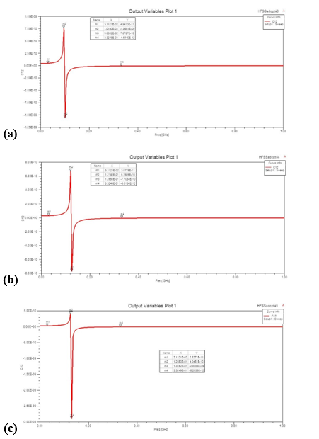
Figure 7: Capacitance versus frequency for the prototype for the maximum capacitance value for (a) without (b) 40µm (c) and 50µm of air gap
The meticulous optimization of electrodes addresses the critical requirement of maintaining a low gap thickness. With a recommended air gap thickness of 50µm, corresponding to 22pF of equivalent capacitance, the resonance frequency increases to 126MHz. Fig. 7 (c) visually captures the impact of air gap thickness on capacitance versus frequency.
Discussion Summary
The study's meticulous measurements successfully validated the development process, demonstrating that the estimated electrical behavior aligns precisely with simulated specifications. Various prototype stages have continuously enhanced trimmer performance, demonstrating its potential to meet and exceed MRI application requirements. The chosen materials exhibit remarkable stability over a diverse frequency range.
However, the introduction of an air gap further refines the prototype, as illustrated in Fig. 7. This refinement leads to a reduction in capacitance as frequency increases, as evidenced by simulations and measurements. At 75MHz, the breakdown voltage, estimated at 3.7kV in simulation, impressively matches experimental results of 4.1kV.
In conclusion, this prototype, with its validated capacitance range and nominal voltage, stands as a pioneering innovation poised to significantly impact high-frequency MRI applications.
Conclusions
According to this study, the prototype meets specifications, marking a significant advancement in competitive trimmers for high-frequency MRI applications. Beyond validation, the section provides forward-looking insights into potential research directions, highlighting the pivotal role of Emerging Technologies and Innovative Research in advancing adjustable capacitors for optimizing high-frequency MRI systems.
The seamless fusion of empirical research and electrostatic principles has yielded a groundbreaking design for new trimmers tailored to MRI applications. Propelled by a pioneering modeling approach, deeply rooted in theoretical frameworks and rigorously validated numerically, the study propels advancements in performance, cost-effectiveness, and flexibility. Through systematic prototyping, the research achieves tangible improvements in electrical strength, quality factor, and resonance frequency.
Various dielectric shapes, electrode applications, and assembly components are meticulously examined to prove the prototype's suitability for high-frequency MRI applications and set the stage for further research. These include resonance optimization, metallization strategies, and mitigation of high-frequency electromagnetic phenomena. This research supports the continuous evolution of adjustable capacitors by emphasizing emerging technologies and innovative research, which ensures their adaptability to advanced MRI sytems' dynamic landscapes.
References

condensateur ajustable amagnétique RF haute tension pour l’IRM.- Jebri, Z., Taleb Ali, M., & Bord Majek, I. (2023).Investigating the effects of uniaxial pressure on thepreparation of MgTiO3–CaTiO3 ceramic capacitors for MRI systems. The Journal of Engineering, 2023(9), e12300.
- Jebri, Z., Bord-Majek, I., Bardet, M., & Ousten, Y. (2023). FEM simulation-based development of a new tunable non-magnetic RF high voltage capacitor for the new generation of MRI. The Journal of Engineering, 2023(1), e12204.
- Jebri, Z., Majek, I. B., Delafosse, C., Pasquet, C., & Ousten, Y. (2018, May). A new non-magnetic trimmer for the magnetic resonance imaging system. In 2018 7th International Conference on Modern Circuits and Systems Technologies (MOCAST) (pp. 1-5). IEEE.
- Jebri, Z., Majek, I. B., Delafosse, C., & Ousten, Y. (2018, September). Electrical modeling approach and manufacturing of a new adjustable capacitor for medical applications. In 2018 7th Electronic System-Integration Technology Conference (ESTC) (pp. 1-5). IEEE.