

Journal of Sensor Networks and Data Communications(JSNDC)
ISSN: 2994-6433 | DOI: 10.33140/JSNDC
Impact Factor: 0.98


Research Article - (2025) Volume 5, Issue 2
Enhancing Biometric Landmark Detection Optimizing Imaging Acuity
Received Date: Feb 10, 2025 / Accepted Date: Mar 31, 2025 / Published Date: May 05, 2025
Copyright: ©Â©2025 Greg Passmore. et al. This is an open-access article distributed under the terms of the Creative Commons Attribution License, which permits unrestricted use, distribution, and reproduction in any medium, provided the original author and source are credited.
Citation: Passmore, G., Bredow, S. (2025). Enhancing Biometric Landmark Detection Optimizing Imaging Acuity. J Sen Net Data Comm, 5(2), 01-13.
Abstract
UVB imaging, operating within the 280–315 nm range, has historically suffered from low contrast and limited acuity due to fundamental challenges in optical components and sensor technology. In our lab, we conducted extensive experimentation to identify and optimize the key factors influencing image quality in this spectral range. Through systematic evaluation of lens materials, optical coatings, filter designs, and sensor architectures, we developed high-precision solutions to mitigate optical losses, reduce aberrations, and enhance signal capture efficiency.
Our research emphasized the importance of selecting UV-transparent lens materials, such as fused silica and calcium fluoride, to minimize absorption while carefully managing chromatic aberration. We assessed the impact of interference filters in controlling spectral selectivity and blocking unwanted radiation that could degrade image contrast. Additionally, we investigated the effectiveness of various sensor technologies, including back-illuminated CCDs and UV-enhanced CMOS detectors, to maximize quantum efficiency and maintain stability under prolonged UV exposure. Through controlled testing and iterative system refinement, we identified the optimal configurations that consistently produced high-resolution, high-contrast UVB images. Our findings demonstrate that achieving superior imaging performance in the UVB spectrum requires a precise balance of optical material selection, filter design, and sensor optimization. By carefully integrating these components into a cohesive system, we successfully developed an imaging platform capable of delivering exceptionally high-resolution, high-contrast results on a consistent basis.
Keywords
UVB imaging, 280–315 nm, UV-transparent optics, interference filters, spectral selectivity, UV-enhanced CMOS, quantum efficiency, sensor optimization, signal capture efficiency.
Introduction
This paper is intended to communicate our results in pursuing high-acuity UVB imaging, with the goal of providing practical insights that may assist others working in the field. Our focus is on the technical challenges and optimizations required to achieve high-resolution, high-contrast imaging in the 280–315 nm range, where conventional optical and sensor technologies often fall short. This is a practical study rather than a theoretical exploration or a regulatory discussion. The emphasis is on the implementation and validation of techniques that have demonstrated effectiveness in real-world UVB imaging applications. We aim to provide clear, actionable results based on direct experimentation with optical components, sensor configurations, and image processing methodologies. Mathematical treatments are included where necessary to clarify key principles and to assist in system design and performance evaluation. These formulations are provided not as theoretical derivations but as practical tools for understanding image formation, noise management, and calibration. Additionally, the mathematical descriptions are structured in a way that facilitates direct implementation in code, should readers choose to integrate these methods into their own imaging systems.
By presenting these results, we hope to provide a technical reference that can streamline development efforts, reduce experimental guesswork, and improve the reproducibility of high-precision UVB imaging across different applications. UV photography is not new and there are talented artists, such as the Paris-based photographer Pierre-Louis Ferrer, who does beautiful work. However, this paper deals with less artistic and more practical aspects of UV imaging, largely for biometrics and visual effects. This paper also discusses the actual process and components needed to acquire high acuity.
High Acuity Challenges
Capturing ultraviolet (UV) imagery with high acuity poses significant challenges due to the unique properties of UV light and the specific demands of imaging systems designed to capture it. Despite these obstacles, the acquisition of high-acuity UV images is of paramount importance for various applications, especially in fields such as medicine and security, where clear imaging of chromophores is crucial. Chromophores, the molecules responsible for color in substances, play a significant role in diagnosing diseases and verifying authenticity and identity, making the quality of UV imagery critical.

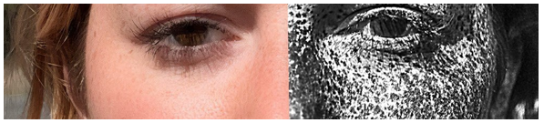
Typical Low Acuity UV Skin Image [1]
In the pursuit of enhancing the quality of UV imagery, our laboratory embarked on a series of experiments and adjustments to the standard imaging setup. Through our investigations, we identified the necessity of employing exceptionally narrow bandpass filters, with the specific frequency dependent on the specific imaging requirements. Our focus has been at the upper end of UVB. These narrow filters are required in isolating the very specific wavelengths of UV light required for our imaging purposes. Such narrow filtering significantly reduces the noise and improves the clarity of the resultant images. Furthermore, the choice of materials used in the construction of the imaging lines proved to be a decisive factor in achieving high acuity in UV imagery. Traditional imaging systems often utilize glass in their lenses and other optical components; however, glass has limited UV transmission capabilities, which can significantly hinder the effectiveness of UV imaging. Our work quickly confirmed that lenses made of quartz, rather than glass, substantially improved the transmission of UV light through the imaging system. Quartz's superior UV-transmissive properties allow for a more efficient capture of UV light, thereby enhancing the overall quality of the images.
The integration of exceptionally narrow bandpass filters together with high-quality quartz lenses culminated in a remarkable improvement in the acuity of UV images captured in our lab. The advancements we achieved in UV imaging technology have yielded consistent imagery of substantially higher quality than typically seen in our field. This process not only demonstrates the potential for reliable improvements in UV imaging techniques, but also underscores the importance of material choice and precise wavelength selection in capturing high quality UV images. Such enhancements in UV imaging capabilities are poised to assist applications requiring detailed analysis and visualization of chromophores, including, but not limited to, biometrics, medical diagnostics, forensic analysis, and the verification of documents and products.
Extremely Narrow Bandpass Filters
We are going to spend some time on filters because careful filter selection is critical to obtaining good imaging quality. We have tested dozens of filters with dramatically different results. What we learned was the manufacture of these filters, and their purported bandpass values are highly variable. To determine how suitable they were, we used a UV sensitive spectrophotometer to identify the results. These filters also age under use and drift in their cutoff values. The manufacture of extremely narrow bandpass filters for ultraviolet is a highly specialized process, designed to achieve precise control over the transmission of specific UV wavelengths while blocking all others. In many cases, we needed to stack filters to further block spectral areas causing hazing. The complexity of manufacturing these filters arises from the need for high precision in both the design and fabrication phases, ensuring that they meet stringent performance criteria.

Our Process Exhibiting Fine Detail and No Hazing
Bandpass Filters
Design and Material Selection
The design starts with the selection of appropriate materials that exhibit high transmission in the UV range and the desired spectral characteristics. Materials must be chosen for their optical properties, including refractive index contrast and transparency at the target UV wavelengths. High-purity materials such as fused silica, titanium dioxide (TiO2), and silicon dioxide (SiO2) are commonly used for their favorable optical properties and stability. The choice of materials directly affects the filter's efficiency, temperature stability, and longevity.
Deposition Techniques
Fabrication involves advanced deposition techniques to apply multiple thin layers of optical materials onto a substrate. Physical Vapor Deposition (PVD) methods, such as sputtering and evaporation, are frequently used. These techniques allow for precise control over the thickness and composition of each layer, which is necessary for achieving the narrow bandpass characteristics. The deposition process must be carefully controlled to ensure uniformity across the filter surface, since variations lead to inconsistencies in the filter's optical performance.
Coating Design
The heart of the narrow bandpass filter's performance lies in its multilayer coating design [2]. These coatings consist of alternating layers of materials with different refractive indices, tailored to create constructive and destructive interference for specific wavelengths of light. This is an active area of research, due, in part, to the complexity of manufacturing [3]. Designing these coatings requires sophisticated software capable of modeling the optical behavior of multiple layers and predicting how they will interact with UV light. The goal is to enhance the transmission of a narrow wavelength band while attenuating unwanted wavelengths through reflection, absorption, or destructive interference.
Quality Control and Testing
For quality imaging, we have found 5 nm to be required. Quality control and testing are critical parts of the manufacturing process, ensuring that each filter meets the expected specifications. This includes measuring the filter's transmission properties using spec-trophotometers capable of accurately assessing performance in the UV range. Filters are tested for their central wavelength accuracy, bandwidth, and out-of-band rejection to ensure they perform as designed. Environmental testing is also conducted to evaluate the filter's durability and stability under various conditions, such as temperature changes and exposure to UV radiation over time.
Challenges
Producing bandpass filters with such narrow bandwidths, such as our 5 nm requirement, presents several challenges, including the need for extremely uniform thin-film layers, the management of thermal effects that could alter the optical properties of the materials, and ensuring long-term stability and reliability of the filters under operational conditions. Innovations in materials science, thin-film deposition technologies, and optical design continue to overcome these challenges, pushing the boundaries of what is possible in optical filtering.
Quartz Lenses
Quartz or fluorite lenses are required for UV imaging of any quality. We use, and will concentrate on, quartz. Let’s look at why glass lenses are problematic. To understand the mathematics behind the choice of quartz versus glass in the context of UV imaging, we need to consider the optical properties that influence their performance in transmitting ultraviolet light. The key factors include the refractive index, transmission spectrum, and the absorption coefficients of these materials. These properties determine how well light of different wavelengths, especially in the UV spectrum, passes through quartz and glass.
Refractive Index
The refractive index (n) of a material describes how light bends as it enters the material from a vacuum or air. It's defined as:
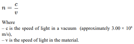
For UV imaging, the refractive index influences the lens design and focusing capability. Quartz (fused silica) and certain types of glass (like borosilicate) have different refractive indices, affecting their optical performance.
Transmission and Absorption Coefficient
The transmission spectrum of a material shows how its transmittance varies across different wavelengths. The absorption coefficient α, which is wavelength-dependent, is crucial for understanding how materials absorb light at UV wavelengths. The Beer-Lambert law can describe the intensity of light (I) transmitted through a material as a function of the incident light intensity I0, the material's absorption coefficient (α), and the thickness (d) of the material:
I = I0e−αd
Quartz has a significantly lower absorption coefficient for UV wavelengths compared to most types of glass, making it more transparent to UV light and, thus, more suitable for UV imaging applications.
UV Transmission Efficiency
To quantify the difference in UV transmission between quartz and glass, consider a simplified example where we compare the transmission efficiency of quartz and typical glass at a UV wavelength of 250 nm, given their respective absorption coefficients.
– Suppose quartz has an absorption coefficient of 0.1cm−1 at 250 nm, while typical glass has 10cm−1 at the same wavelength.
– For a 1 mm (0.1cm) thick sample, the transmission (T), calculated as T =I/I0 =e−αd, would be:
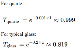
This simplified calculation illustrates that quartz transmits 99% of UV light at 250 nm, making it almost completely transparent to UV, whereas typical glass only transmits 37%, significantly attenuating UV light. The manufacturing of quartz lenses represents a niche domain and is charecterized by its rarity and complexity. This complexity arises from several intrinsic and extrinsic factors related to the physical properties of quartz, the precision required in lens manufacturing, and the specialized applications that necessitate the use of quartz lenses.
Quartz Stock
The quest for perfect quartz stock to manufacture high quality lenses is fraught with difficulties, stemming from both the natural characteristics of quartz and the stringent demands of optical applications. Finding quartz stock that meets the exact specifications required for lens production involves navigating a series of challenges related to the material’s purity, clarity, and internal structure. These factors play a crucial role in determining the final optical quality of the lenses, making the selection process both critical and complex.
Purity and Clarity
Quartz used in lens manufacturing must be of exceptional purity and clarity. Any impurities, such as metallic ions or other mineral inclusions, can significantly affect the optical properties of the quartz, leading to absorption or scattering of light that degrades the performance of the lens. The quest for pure quartz is complicated by the natural formation process of quartz, which often involves the incorporation of impurities from the surrounding environment. As a result, only a small fraction of naturally occurring quartz meets the high standards required for optical lens production. Synthetic quartz offers an alternative with potentially higher purity levels, but synthesizing quartz that is free from impurities and defects at a molecular level is an intricate and costly process.
Internal Stress and Structural Defects
Beyond purity and clarity, the internal structure of quartz stock must be free from stress and defects. Internal stresses can arise during the quartz's formation or as a result of post-formation processes, such as cutting or treatment. These stresses can lead to birefringence, where the refractive index varies within the material, causing optical distortion that is unacceptable in precision lens applications. Similarly, structural defects such as dislocations, twinning, or micro cracks can scatter light or create weak points in the lens, compromising its durability and optical performance. Identifying quartz stock with minimal internal stress and defects requires sophisticated analysis techniques, further complicating the selection process.
Homogeneity
For high-quality lens production, the quartz stock must also ex-hibit homogeneity in its physical and optical properties across the entire piece. Inhomogeneities can lead to variations in optical per¬formance across the lens, affecting its ability to focus light uni¬formly. Achieving homogeneity is particularly challenging given the natural variability of quartz and the potential for inclusions or structural anomalies. The requirement for homogeneity narrows the selection of suitable quartz stock, as each piece must be care¬fully evaluated to ensure it meets these criteria.
Size and Shape Considerations
The size and shape of the quartz stock are also critical factors, especially for large or complex lens designs. Finding large enough pieces of quartz that are both of sufficient quality and free from imperfections becomes increasingly difficult as the size require-ments increase. Additionally, the initial shape of the quartz stock can impact the efficiency of the lens manufacturing process, with certain shapes offering more usable material and reducing waste.
Economic and Environmental Factors
Finally, the economic and environmental considerations asso-ciated with sourcing perfect quartz stock cannot be overlooked. High-quality quartz is a finite resource, and the competition for the best materials can drive up costs. Moreover, the mining and processing of quartz must be done responsibly to minimize envi-ronmental impact, adding another layer of complexity to the pro¬curement process.
Origin of Lens Quartz
The quest for the highest quality quartz for lens manufacturing specifically targets the material's optical purity, low internal stress, and homogeneity. These criteria are crucial due to the stringent requirements of optical applications, where even minor imperfections can significantly affect lens performance. The sites renowned for producing quartz, while meeting these exacting standards for lens production, include the following global regions.
Brazil: The quartz from Brazil, notably from the Minas Gerais region, is celebrated for its exceptional optical clarity and minimal impurities. This makes it an excellent choice for manufacturing lenses which require high transmission rates and minimal optical distortion, including precision instruments and high-power laser systems.
The United States: 1) The state of Arkansas is distinguished by its production of high-quality quartz crystals. These crystals are sought after for their low levels of internal stress and high clarity, essential attributes for creating lenses used in demanding optical applications. 2) Herkimer County in New York, famous for its "Herkimer diamonds," produces double-terminated quartz crystals with remarkable clarity, also suitable for specialized optical components.
Madagascar: While known for its gemstone-quality colored quartz, Madagascar also produces clear quartz variants. The optical grade quartz from this region is valued for lens manufacturing, especially in applications where purity and aesthetic qualities are paramount.
Switzerland: Quartz from the Swiss Alps is prized for its exceptional purity and structural integrity. Swiss quartz is ideal for the production of optical lenses that require precise light transmission and minimal birefringence, a critical factor in high-precision optical systems.
Russia: The Ural Mountains in Russia yield quartz crystals with notable optical and electronic properties. This quartz is utilized in various industrial applications, including the manufacturing of lenses that demand high optical clarity and consistency.
In lens manufacturing, the provenance of quartz is a key factor in determining the quality of the final product. However, it's the specific qualities of the quartz—such as purity, clarity, and the absence of internal stresses and defects—that ultimately dictate its suitability for optical use. With advancements in synthetic quartz production, manufacturers now have the option to use artificially produced quartz that can meet, or even exceed, the purity levels of natural quartz, providing a reliable alternative for the most demanding optical applications. This synthetic quartz is engineered to possess minimal internal stresses and high homogeneity, making it increasingly preferred for manufacturing a wide range of optical lenses, from precision microscopy to high-power laser optics.
Intrinsic Properties of Quartz
Quartz, a crystalline form of silica, is renowned for its exceptional optical clarity, high melting point, and resistance to thermal shock, making it an ideal material for lenses that operate under extreme conditions, including high temperatures and UV light exposure. However, these same beneficial properties contribute to the challenges of lens manufacturing. The hardness and brittleness of quartz demand specialized equipment and techniques for shaping and polishing, significantly differing from those used for more common glass lenses. Moreover, the high melting point of quartz complicates the molding process, requiring the use of high temperature furnaces capable of consistently maintaining conditions that will not compromise the material's integrity or optical properties.
Specialized Equipment and Skilled Labor
The equipment used for polishing quartz lenses must be capable of maintaining precise control over speed, pressure, and temperature, parameters that are critical for achieving the desired surface finish without causing damage. Furthermore, the process requires skilled technicians who understand the nuances of working with quartz and can adjust the polishing process based on the material's response. The combination of specialized equipment and skilled labor adds to the complexity and cost of producing quartz lenses.
Hardness and Brittleness of Quartz
Quartz, composed primarily of silicon dioxide, exhibits a Mohs hardness rating of 7, making it significantly harder than many other materials used in optical manufacturing. This high degree of hardness contributes to the material's durability and resistance to scratching, qualities that are beneficial for the final product, but make the polishing process more challenging. The hardness requires the use of specialized abrasive materials and techniques to gradually smooth the quartz surface without causing cracks or chips. Additionally, quartz's brittleness—a characteristic that makes it prone to chipping or breaking under stress—necessitates careful handling during the polishing process to avoid damaging the lens.
Achieving Optical-Quality Surface Finishes
Achieving a high-quality finish on quartz lenses requires multiple stages of polishing, each using finer abrasives to progressively smooth the surface to the desired degree of perfection. This process is not only time-consuming but also requires precise control and constant monitoring to ensure that each stage of polishing contributes to the overall surface quality without introducing new imperfections. Wavelengths ranging from 280 nm to 315 nm impact the surface roughness requirements. The surface quality, particularly surface roughness, plays a large role in determining the efficiency and quality of imaging due to its influence on light scattering.
Theoretical Framework
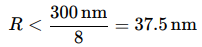
The scattering of light from a surface increases as the surface becomes rougher, or as the wavelength of the light decreases. This relationship is quantified in the context of the Rayleigh criterion for surface roughness (R), which can be expressed in terms of the wavelength (λ) of the light. According to this criterion, a surface is considered "optically smooth" if its roughness is less than one-eighth of the wavelength of the incident light:

Given this, for UVB light at the approximate midpoint of its range, say 300 nm, the maximum allowable roughness for a surface to remain "optically smooth" and minimize scattering is:
Surface Roughness Requirements
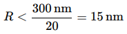
Minimizing scattering is crucial, so the surface roughness must be an even smaller fraction of the UV wavelength. If we consider a more stringent requirement, such as:

then, for a UVB wavelength of 300 nm, the roughness limit becomes:
300nm
Thermal Damage and Chemical Reactivity
Quartz is sensitive to thermal shock and can be damaged by sudden changes in temperature, a risk that is present during the polishing process due to friction-generated heat. Managing the temperature to prevent thermal damage without compromising the effectiveness of the polishing process is a delicate balance. Additionally, the chemical reactivity of quartz must be considered when selecting polishing compounds and lubricants, as some chemicals can alter the surface properties of quartz or leave residues that impair optical clarity. Chemical reactivity is a two-way street, in that there are beneficial and detrimental chemicals. The quartz is significantly influenced by its chemical purity and the presence of specific impurities or dopants. Quartz, or silicon dioxide (SiO2), in its purest form, is highly transparent across a wide spectral range. However, the presence of certain chemicals, either as residual impurities or intentional dopants, can affect its optical properties.
Protecting Optical Quartz
Quartz’s optical properties can be modified during manufacturing and usage due to interactions with various substances, from benign agents to aggressive chemicals. This section explores examples of both categories, highlighting substances that quartz may encounter and their potential impact on its optical qualities.
Quartz Modifying Chemicals and Effects
Various chemical impurities and intentional dopants in quartz in¬fluence its optical properties, particularly in UVB imaging applica¬tions where high transparency and stability are essential. The pres¬ence of hydroxyl ions (OH−) primarily affects infrared absorption, but their removal through dehydration processes can also improve deep ultraviolet (DUV) transmission by reducing structural defects and water-related impurities. However, aggressive dehydration can introduce lattice defects that degrade UV transparency over time, particularly in the form of UV-induced darkening.
Aluminum (Al3+) in quartz plays a dual role. It introduces absorption bands, particularly in the UVC and UVB range, reducing transmission efficiency. However, controlled aluminum doping improves resistance to radiation-induced defects by stabilizing the quartz lattice, reducing the formation of UV-induced color centers. Managing aluminum content carefully allows for a balance between optical clarity and durability under prolonged UV exposure.
Titanium (Ti 4+) contamination in quartz leads to unwanted absorption bands extending into the UV range, negatively impacting UVB imaging by reducing transmission efficiency and image contrast. Unlike aluminum, titanium does not provide structural stabilization benefits, making its minimization essential for achieving high optical clarity in UVB applications.
Sodium (Na+), an alkali metal, is often introduced during manufacturing. It contributes to the formation of color centers when exposed to UV radiation. These defects cause progressive darkening, reducing optical transmission over time. High-purity manufacturing processes, including the use of synthetic fused silica, aim to minimize sodium and alkali content to ensure long term optical stability in UVB imaging systems.
Other alkali metals, including lithium (Li+) and potassium (K+), exhibit similar effects to sodium, increasing the risk of defect formation and color center generation. Their presence can lead to increased fluorescence and scattering, further degrading UVB imaging performance. High-purity fused silica with minimal alkali metal content is preferred to ensure long-term optical reliability.
Hydrogen (H+) impurities form hydrogen-related color centers that degrade UV transmission, particularly under high-energy UV exposure. These defects contribute to increased absorption and scattering, negatively affecting image contrast and resolution. Specialized purification and annealing techniques are used to reduce hydrogen content and enhance long-term stability.
Boron (B 3+) is sometimes introduced to modify quartz's thermal and mechanical properties, improving manufacturability. However, boron alters the quartz lattice structure, potentially introducing absorption bands and impacting UV transparency. For high-precision UVB imaging, minimizing boron content is preferred to maintain spectral clarity.
Image Sensors
Availability
UV sensitive sensors are not commonly available, since most cameras are typically designed to capture images within the visible light spectrum, approximately from 400 nm to 700 nm. To ensure image quality and protect the sensor, manufacturers install glass filters or coatings that block out ultraviolet (below 400 nm) and infrared (above 700 nm) light. For UV imaging, a sensor without these filters in place is required.
UV Filter Removal
There are few cameras made specifically for UV imaging. Those that exist tend to be very expensive and in our testing, did not perform as well as modified prosumer cameras. This is not to say there are not affordable, high quality options, we just did not find any, despite purchasing numerous industrial cameras claiming to meet our requirements. Commercial prosumer cameras offered the best image quality in our testing. However, consumer and prosumer digital cameras are designed to capture images within the visible light spectrum, approximately from 400 nm to 700 nm. To ensure image quality and protect the sensor, manufacturers install filters that block out ultraviolet (below 400 nm) and infrared (above 700 nm) light. The UV filter, in this context, is a piece of glass or coating applied over the sensor that prevents UV light from reaching it. Removing the ultraviolet (UV) filter from a camera sensor involves intricate procedures that, if not performed correctly, pose several safety concerns for the operator. These concerns primarily stem from the handling of delicate camera components and the use of tools and chemicals. We would recommend having a specialist perform the task if you decide to use prosumer cameras.
Noise Challenges
The challenge of noise in high-resolution UV sensors is a key issue that impacts the quality of UV imaging. This noise, which can manifest as random variations in pixel values that do not correspond to the actual light intensity, detracts from the sensor's ability to accurately capture the details of a scene or object. The issue is particularly pronounced in UV sensors for a couple of key reasons related to the nature of UV photons and the operational characteristics of the sensor itself.
High Energy of UV Photons
UV photons carry more energy compared to visible light photons due to their shorter wavelengths. When these high-energy photons strike the sensor's photodetector material, typically silicon, they can generate a surplus of electron-hole pairs compared to photons in the visible spectrum. This excess can lead to an increase in the baseline noise level of the image, known as "shot noise," which is a fundamental noise source arising from the discrete nature of light itself. The higher energy of UV photons means that shot noise can be more significant in UV imaging, potentially overwhelming subtle details in the captured images and reducing the overall image quality and resolution.
Thermal Effects on Sensor Performance
The operation of UV sensors, particularly those designed for high-resolution imaging, inherently generates heat. This heat production is due in part to the denser packing of electronic components required for high-resolution and the increased power consumption associated with high-performance imaging operations. The heat generated by the sensor and its supporting electronics can lead to an increase in dark current, a form of noise that occurs even when the sensor is not exposed to light. Dark current is essentially a small, but significant, background signal that is present in all photodetectors and increases exponentially with temperature. As the sensor temperature rises, the dark current increases, adding a constant background noise level that can obscure the detection of low-light UV signals and degrade the dynamic range and signal-to-noise ratio (SNR) of the sensor. This thermal noise can be particularly challenging in environments where cooling options are limited, or in applications requiring prolonged use of the UV sensor, which can allow heat to build up over time.
Mitigating Thermal Noise
Addressing the challenges of noise in high-resolution UV sensors involves both hardware and software strategies. On the hardware front, cooling mechanisms such as thermoelectric coolers (TECs) are often integrated into the camera design to maintain the sensor at a stable, lower temperature, thereby reducing dark current and thermal noise. Passive cooling methods and heat sinks may also be employed to dissipate heat more effectively from the sensor and electronics.
Sensor Cooling
Sensor cooling is a useful aspect of managing noise in high-acuity imaging. Cooling reduces sensor temperature, which directly impacts the amount of dark current — a significant source of noise in digital imaging. The mathematical relationship between sensor temperature and dark current, along with the effectiveness of cooling mechanisms, can be explored to understand how cooling contributes to enhanced imaging performance.
Dark Current and Temperature
Dark current is the small amount of current that flows through a photodetector even in the absence of light. It is generated by the thermal excitation of electrons, which creates electron-hole pairs without the need for photon input. The rate at which these pairs are generated increases with temperature, leading to a higher dark current as the sensor gets warmer.
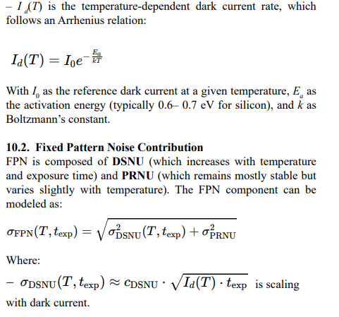
The relationship between dark current and temperature can be approximately modeled by the Arrhenius equation, which is given
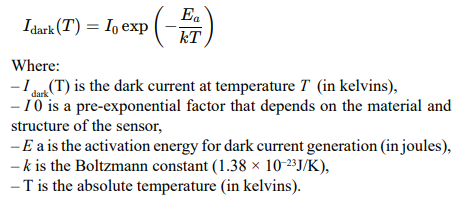
This equation demonstrates that dark current exponentially increases with temperature, highlighting the importance of cooling for noise reduction [4].
Sensor Cooling Techniques
Cooling techniques aim to reduce the sensor's temperature, thereby lowering the dark current and associated noise. Common cooling methods include:
Thermoelectric Coolers (TECs): TECs, or Peltier devices, use the Peltier effect to transfer heat away from the sensor. The effectiveness of a TEC can be quantified by the amount of heat it can move (Q), given by:
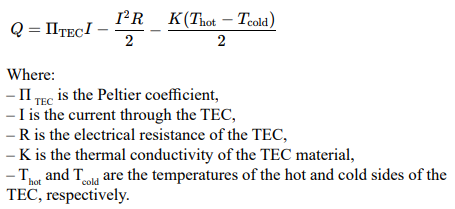
Adjusting the current I allows control over the amount of heat transferred, thus controlling the cooling effect.
Liquid Cooling: Involves circulating a coolant around the sensor or camera system to absorb and dissipate heat. The efficiency of liquid cooling can be analyzed through the principles of heat transfer, particularly the heat capacity of the coolant and the flow rate.
Modeling of Cooling Efficiency
The effectiveness of cooling in reducing dark current can be quantitatively modeled by integrating the Arrhenius equation with the heat transfer equations governing the specific cooling method employed. Dark current in imaging sensors follows an exponential dependence on temperature, described by the Arrhenius relation:
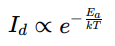
Where Id is the dark current, Ea is the activation energy, k is Boltzmann’s constant, and T is the absolute temperature. This equation highlights the strong dependence of dark current on temperature, making thermal management a crucial factor in optimizing sensor performance.
For thermoelectric coolers (TECs), the achievable temperature reduction is influenced by multiple interacting factors. The cooling power provided by the TEC is proportional to the electrical current supplied, while its efficiency depends on material properties such as the Seebeck coefficient, electrical resistance, and thermal conductivity. The net cooling effect is further constrained by external conditions, including the ambient temperature, heat sink efficiency, and thermal resistance between the sensor and its cooling interface. The governing heat transfer equations for TEC performance can be expressed as:
Where Qc is the heat absorbed from the sensor, α is the Seebeck coefficient, I is the applied current, Tc and Th are the cold and hot side temperatures, R is the electrical resistance, and K is the thermal conductance of the TEC module. This equation captures the balance between Peltier cooling, Joule heating, and heat conduction losses, which ultimately determine the lowest temperature that can be achieved. By integrating these models, it is possible to predict the optimal operating conditions that minimize dark current while maintaining sensor performance and longevity. Excessive cooling, while effective in reducing noise, can introduce other issues such as increased power consumption, condensation risks, and mechanical stress on the sensor due to thermal cycling. In battery-powered or portable imaging systems, cooling efficiency is particularly important, as aggressive cooling can drain power resources rapidly, limiting operational endurance. The ability to fine-tune cooling parameters based on system constraints ensures an optimal balance between power consumption and noise reduction. By evaluating the trade-offs between temperature reduction, sensor performance, and energy efficiency, engineers can design imaging systems that achieve superior image quality while maintaining practical operating conditions. This approach is particularly relevant for scientific, astronomical, and low-light imaging applications, where thermal noise is a primary limiting factor in sensor performance.
Software Noise Reduction
From a software perspective, advanced noise reduction algorithms are applied during or after image capture to filter out noise while preserving the integrity of the UV signal. These algorithms can include spatial and temporal noise reduction techniques, which analyze the noise patterns across different areas of the image or across a sequence of images to distinguish between noise and genuine UV signal.
Dark Current Noise
Dark current noise originates from the thermal motion of charge carriers (electrons and holes) within the sensor, generating a signal even in the absence of light. It is an unavoidable component of the total noise in an image and varies with sensor temperature and exposure time. The dark current noise introduces a baseline level of signal that can obscure true image information, especially in low-light conditions.
Dark Image Calibration
Dark image calibration involves capturing and subtracting a "dark frame" from the actual image to correct for dark current noise [5]. A dark frame is an image captured with the same exposure time and sensor settings as the actual image but with no light reaching the sensor, typically by closing the camera shutter or covering the sensor. This dark frame represents the sensor's dark current response and other fixed-pattern noise sources under those specific conditions [6].
Temperature Matching: Since dark current varies with temperature, it's useful to ensure that the dark frame is captured at the same sensor temperature as the actual image to provide an accurate correction. One advantage of sensor cooling is to minimize variations in ambient temperature.
Multiple Dark Frames: Capturing and averaging multiple dark frames can reduce random noise within the dark frames themselves, leading to a more accurate representation of the dark current noise.
It also provides some understanding of the degree of reliability one can expect. Scaling for Different Exposure Times: We need to capture a dark frame for various exposure times to develop a model of the sensor’s noise characteristics.
Mathematical Basis
The process of dark image calibration can be mathematically described as follows:
To express the dark image calibration process using sigma notation, considering a digital imaging sensor array that's organized in a two-dimensional grid with dimensions M×N, where M is the number of rows (y-direction) and N is the number of columns (x-direction). We can reformulate the signal correction for each pixel in terms of summations over all pixels in both the x and y directions.
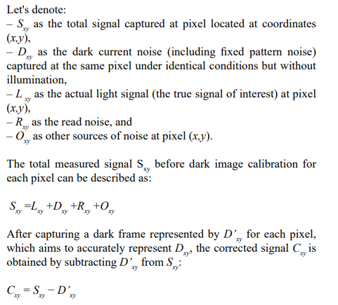
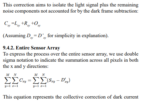
noise across the entire sensor array by summing the corrected signals Cxy for all pixels, enhancing the overall image by reducing the noise attributed to dark current and fixed-pattern noise. It is noteworthy that while this provides a framework for dark image calibration, the effectiveness of this in practice depends on the precise matching of conditions (like temperature and exposure time) between the capture of the actual image and the dark frame, as well as having to make allowances for the uniformity and stability of dark current noise across the sensor. This equation assumes that the dark current noise is additive, and that the dark frame accurately represents the noise characteristics of the actual image capture scenario. The subtraction effectively removes the baseline signal caused by dark current and other constant noise sources, enhancing the signal-to-noise ratio (SNR) and revealing the true image information. This is not a complex process, but it is incredibly useful in actual practice.
Unifying Noise into A Single Metric
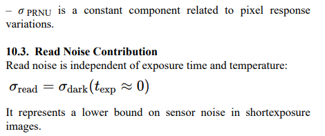
To accurately describe image sensor noise, a single unified metric must account for dark current noise, fixed pattern noise (FPN), and read noise while incorporating their dependence on temperature and exposure time. A practical approach is to express total noise as a function of these parameters, allowing for calibration across different operating conditions.
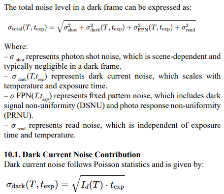
Where:
Final Noise Model and Results
Substituting all components:

Although this topic has greater depth, I have only addressed the areas which proved practical in our application. For those interested in greater technical intricacies, refer to European standards for machine vision, EMVA Standard 1288 Standard for Characterization of Image Sensors and Cameras, 2021.
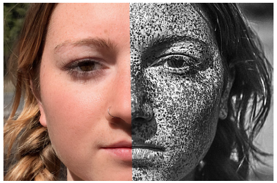
By following the methods above, and paying attention to the intricacies of the optical path and sensor, we have successfully attained imaging results characterized by high acuity and high contrast, as shown in the image above. This outcome underscores the value of attention to detail, especially when compared to previous efforts in the field.
Biometrics
The concept of using chromophores for identification represents a novel approach in the field of biometric identification. Chromophores, molecules that absorb light at specific wavelengths, can be utilized in ways that are inherently resistant to conventional methods of obscuring identity, such as makeup, masks, or even plastic surgery. The key to this technology lies in its reliance on the unique absorption properties of chromophores that are invisible to the naked eye and are inherent in biological tissues or artificially introduced as markers.
Inherent Chromophores in Skin
Human skin contains various natural chromophores, such as melanin, hemoglobin, and water, each absorbing light at different wavelengths. Advanced imaging techniques, such as multispectral or hyperspectral imaging, can detect these unique absorption patterns, providing a "spectral signature" unique to an individual. This signature remains consistent despite surface alterations, offering a robust method for person recognition.
Resistance to Surface Modifications
Conventional disguises like makeup or masks alter the surface appearance without significantly changing the underlying spectral signature of skin's chromophores. Thus, identity recognition systems based on chromophore detection can see "through" such attempts at disguise.
Detecting Subsurface Features
Techniques that target chromophores can reveal subsurface vascular patterns or melanin distributions that are unique to individuals and difficult to alter, even with plastic surgery. These patterns can serve as a form of biometric identification similar to fingerprints but are not easily changed.
Resistance to Concealment
Since these markers are not visible under normal lighting conditions, they offer a form of identification that cannot be concealed through traditional means of disguising appearance. Tests on individuals with plastic surgery, for example, show the same distinctive patterns as the dominate identifiable texture.
Durability Against Physical Changes
Artificial chromophore markers can be placed in dermal layers in such a way that they remain unaffected by external changes, including those resulting from plastic surgery. The markers can be encoded with specific patterns or information that is unique to the individual, providing a reliable means of identification.
Extensions to Hands
Our lab has also tested the backs of hands, for use with ATMs or weapons handling, and found adequate patterning for identification. The method may experience practical limitations however, due to the common use of gloves in cold climates.
Artificial Chromophores
The introduction of artificial chromophores as invisible tattoos or markers offers another avenue for secure biometric identification. These markers can be designed to absorb light in the near-infrared spectrum, making them invisible to the naked eye but easily detectable with the appropriate imaging technology.
Advantages and Ethical Considerations
The use of chromophores for person recognition has distinct advantages, including resistance to traditional methods of identity concealment and the ability to provide secure, non-invasive identification solutions. However, this approach also raises important ethical considerations regarding privacy, consent, and the potential for unauthorized tracking or identification. Ensuring that such technologies are developed and used in a manner that respects individual rights and privacy is a central ongoing debate.
Medical Applications
Ultraviolet (UV) imaging has become a valuable tool in dermatology and biomedical research, offering enhanced ways to detect and analyze skin conditions [7]. One key technique, UV-induced fluorescence dermoscopy, takes advantage of natural and synthetic fluorescent compounds in the skin to improve diagnostic accuracy [8,9]. This approach is particularly useful for identifying tumors, evaluating inflammatory skin diseases, and detecting infections. Beyond dermatology, UV imaging is also being explored for more advanced medical imaging applications. It has shown potential in photoacoustic imaging, which combines UV light with ultrasound to create detailed images of tissues, and multispectral fluorescence imaging, which can help locate tumors more precisely [10,11]. Researchers are also investigating synthetic fluorescent compounds, such as green fluorescent protein (GFP) derivatives, for their potential role in UV protection and as markers for detecting specific biomolecules. Another area of interest is the natural fluorescence of tryptophan, an amino acid found in human skin. Studies have shown that tryptophan fluorescence increases with UV exposure, making it a possible indicator of skin cell growth and repair [12]. These advancements in UV imaging and fluorescence-based detection continue to open new possibilities for improving medical diagnostics and treatments, particularly in dermatology and related fields.
VFX and 3D Reconstruction
One frequent challenge to generating 3D models of skin is a lack of significant texture or landmarks for alignment and depth calibration [13,14]. In the VFX industry, for example, RGB and depth capture is limited to specific areas high in structure, or is often handled using markers or structured light, at the expense of simultaneous RGB acquisition [15,14]. The use of plenoptical camera arrays has been demonstrated, but relies on landmarks for alignment [16]. The absence of these landmarks in the cheeks and forehead leads to drifting alignment. In live capture, where speaking or displaying emotions is important, simultaneous RGB and depth using landmarks greatly decreases the amount of data preparation labor required prior to data usage. Using a UV transparent mirror rig, with both visible light and the RGB capture device, such as a RED Digital Cinema camera, provides for concurrent capture.

Landmarks
Conclusion
We have demonstrated that achieving high-acuity UVB imaging is possible through careful selection of optical components, filters, and sensor technologies. By systematically evaluating lens materials, coatings, and detector architectures, we have developed an optimized approach that minimizes optical losses, reduces aberrations, and enhances signal capture efficiency. These refinements enable significantly improved image contrast and resolution, addressing longstanding challenges in UVB imaging. It is hoped that this paper serves as a valuable resource for those seeking to enhance UV imaging performance across various applications, including biomedical diagnostics, industrial inspection, and environmental monitoring. By detailing key factors that influence image quality and presenting practical methods for mitigating optical limitations, we aim to provide a foundation for further advancements in the field. The insights presented here can assist researchers and engineers in refining their imaging systems, improving data fidelity, and expanding the capabilities of UV imaging technology in both scientific and commercial applications [17].
References
- Ultraviolet Photography. (2025). Wikipedia, The Free Encyclopedia.
- Basu, A., Srivatsa, K. M. K., Chakraborty, T. K., & Bhattacharya, T. K. (2007). Fabrication of narrow bandpass filters for wavelength division multiplexing applications–A feasibility study.
- Tibuleac, S., & Magnusson, R. (1997). Diffractive narrow-band transmission filters based on guided-mode resonance effects in thin-film multilayers. IEEE photonics technology letters, 9(4), 464-466.
- Logan, S. R. (1982). The origin and status of the Arrhenius equation. Journal of Chemical Education, 59(4), 279.
- M., G., W., H., & H., S. (2001). Entropy-Based Dark Frame Subtraction. Image Processing, Image Quality, Image Capture Systems Conference.
- Lin, S., Gu, J., Yamazaki, S., & Shum, H. Y. (2004, June). Radiometric calibration from a single image. In Proceedings of the 2004 IEEE Computer Society Conference on Computer Vision and Pattern Recognition, 2004. CVPR 2004. (Vol. 2, pp. II-II). IEEE.
- Mojeski, J. A., Almashali, M., Jowdy, P., Fitzgerald, M. E., Brady, K. L., Zeitouni, N. C., ... & Paragh, G. (2020). Ultraviolet imaging in dermatology. Photodiagnosis and photodynamic therapy, 30, 101743.
- Svensson, J., Axelsson, J., Johansson, A., Bendsoe, N., Svanberg, K., & Andersson-Engels, S. (2006, October). Multispectral fluorescence imaging for tumor detection and molecular biology. In LEOS 2006-19th Annual Meeting of the IEEE Lasers and Electro-Optics Society (pp. 227-228). IEEE.
- Wu, N. L., Lee, T. A., Wang, S. F., Li, H. J., Chen, H. T., Chien,T. C., ... & Hung, C. F. (2016). Green fluorescent protein chromophore derivative suppresses ultraviolet A-induced JNK-signalling and apoptosis in keratinocytes and adverse effects in zebrafish embryos. Experimental Dermatology, 25(12), 983-990.
- Cox, B. T., Laufer, J. G., & Beard, P. C. (2010). Quantitative photoacoustic image reconstruction using fluence dependent chromophores. Biomedical optics express, 1(1), 201-208.
- Bhat, Y. J., Islam, M. S. U., & Errichetti, E. (2025). Ultraviolet-Induced Fluorescence Dermoscopy, a Novel Diagnostic Technique in Dermatological Practice: A Systematic Review. Indian Dermatology Online Journal, 16(1), 25-39.
- Brancaleon, L., Lin, G., & Kollias, N. (1999). The in vivo fluorescence of tryptophan moieties in human skin increases with UV exposure and is a marker for epidermal proliferation. Journal of investigative dermatology, 113(6), 977-982.
- Gašparovic, B., Morelato, L., Lenac, K., Mauša, G., Zhurov, A., & Katic, V. (2023). Comparing direct measurements and three-dimensional (3D) scans for evaluating facial soft tissue.Sensors, 23(5), 2412.
- Van Lint, L., Christiaens, L., Stroo, V., Bila, M., Willaert, R., Sun, Y., & Van Dessel, J. (2023). Accuracy comparison of 3D face scans obtained by portable stereophotogrammetry and smartphone applications. Journal of medical and biological engineering, 43(5), 550-560.
- Zoss, G., Beeler, T., Gross, M., & Bradley, D. (2019). Accurate markerless jaw tracking for facial performance capture. ACMTransactions on Graphics (TOG), 38(4), 1-8.
- Bradley, D., Heidrich, W., Popa, T., & Sheffer, A. (2010). High resolution passive facial performance capture. In ACM SIGGRAPH 2010 papers (pp. 1-10).
- EMVA Standard 1288 Standard for Characterization of Image Sensors and Cameras. (2021). https:// www. semanticscholar.org/paper/EMVA-Standard-1288Standard-for-Characterization-of/714319fbb026d06202be616615e278 cf003af47d