
Annals of Civil Engineering and Management(ACEM)
ISSN: 3065-9779 | DOI: 10.33140/ACEM


Research Article - (2025) Volume 2, Issue 3
Engineering Design and Construction of Cement Double Section Pillar
Received Date: Jul 08, 2025 / Accepted Date: Sep 03, 2025 / Published Date: Sep 15, 2025
Copyright: ©Ã??Ã?©2025 Rabiu Ahamd Abubakar. This is an open-access article distributed under the terms of the Creative Commons Attribution License, which permits unrestricted use, distribution, and reproduction in any medium, provided the original author and source are credited.
Citation: Abubakar, R. A. (2025). Engineering Design and Construction of Cement Double Section Pillar. Ann Civ Eng Manag, 2(3), 01-05.
Abstract
This study focused on the engineering design and construction of a cement pillar to evaluate its structural integrity and load-bearing capacity. The design phase involved selecting an optimal cement mix ratio, calculating dimensions, and assessing factors like curing time and reinforcement needs. During construction, standardized methods were followed to ensure consistency in material composition and structural stability. After curing, the pillar was subjected to incremental load tests to determine its compressive strength, deformation behavior, and failure threshold. Results indicated that the constructed pillar achieved a maximum compressive strength of 43.8 MPa before failure. The findings provided valuable data on the pillar's load resistance and structural performance, offering insights for potential improvements in future designs and applications.
Keywords
Cement Pillar, Concrete Column, Structural Support, Load-Bearing Pillar, Vertical Support, Concrete Structure, Reinforcement, Load Distribution, Column Design
Introduction
Cement pillars, as integral components of numerous structural systems, have been extensively employed in construction for centuries [1,2]. These versatile structures, capable of withstanding significant loads, play a crucial role in supporting buildings, bridges, and other infrastructure [3]. The design and construction of cement pillars involve a meticulous process that considers various factors, including material properties, load-bearing capacity, and environmental conditions [4,5]. The design phase entails determining the optimal dimensions, reinforcement requirements, and concrete mix proportions to ensure the pillar's structural integrity [6,7]. This process often involves the utilization of advanced analysis techniques, such as finite element analysis, to accurately predict the pillar's behavior under various loading scenarios [4,8]. Additionally, adherence to relevant design codes and standards, such as those provided by the American Concrete Institute (ACI) and the European Committee for Standardization (CEN), is essential to guarantee safety and durability [1,2]. Once the design is finalized, the construction phase commences, involving the careful execution of formwork installation, reinforcement placement, and concrete pouring [9,10]. Proper curing and maintenance procedures are crucial to achieve the desired strength and durability of the concrete [10,11]. In recent years, innovative construction techniques, such as precast concrete and slip-forming, have been adopted to improve efficiency and quality [4,12]. The performance of cement pillars is influenced by several factors, including the quality of materials, workmanship, and environmental exposure [4,13]. To assess the long-term performance of these structures, regular inspection and maintenance are necessary to identify and address potential deterioration mechanisms, such as cracking, corrosion, and alkali- silica reaction [4,14]. In conclusion, the design and construction of cement pillars is a complex process that requires careful consideration of numerous factors. By adhering to established design principles, employing quality materials, and implementing sound construction practices, engineers can ensure the safety, durability, and long-term performance of these vital structural elements.
Conceptual Design
Concrete pillars are fundamental structural elements in various construction projects, providing support and stability to buildings and infrastructure. The design and construction of these pillars require careful consideration of factors such as load-bearing capacity, durability, and aesthetics. This conceptual design outlines the key steps involved in the design and construction of a cement pillar, incorporating relevant industry standards and best practices. The design considerations involve the following.
Load Determination
The initial step in the design process is to accurately determine the loads that the pillar will be subjected to. These loads include dead loads (self-weight of the pillar and superimposed dead loads), live loads (occupancy loads, equipment loads), and environmental loads (wind, seismic, and thermal loads). Load calculations should adhere to relevant building codes and standards, such as the American Concrete Institute (ACI) code [15]. The material selected is concrete, and is the primary material used for pillars, and its strength and durability can be tailored by adjusting the mix proportions of cement, aggregates, and water. Additionally, steel reinforcement is often incorporated to enhance the tensile strength and ductility of the concrete [16]. Structural analysis is performed to determine the internal forces (axial forces, bending moments, and shear forces) acting on the pillar under various load combinations. This analysis is carried out using computer-aided design (CAD) software. The results of the analysis are used to design the cross- sectional dimensions and reinforcement requirements for the pillar. The durability is a critical consideration for concrete structures, particularly those exposed to harsh environmental conditions. Proper design and construction practices, including the use of high-quality materials and adequate cover for reinforcement, which significantly improve the durability of concrete pillars. Additionally, protective coatings or treatments may be applied to further enhance durability [17].
Design
Designing a cement (or reinforced concrete) pillar requires determining factors like its load-bearing capacity, dimensions, reinforcement needs, and overall structural safety. Here’s a simplified guide with necessary formulas to design a basic cement pillar (concrete column).
Determine Loads on the Pillar
• Dead Load (DL): Includes the weight of the building materials above the column.
• Live Load (LL): Includes movable loads like people, furniture, etc.
• Ultimate Load (U): The maximum design load to ensure safety.
U = 1.5×(DL + LL) (1)
Select Column Dimensions
• The column has rectangular base with width b and depth d, and circular with diameter D.
• Start by estimating dimensions based on thumb rules or architectural considerations. Later, dimensions can be verified using load calculations.
Calculate Cross-Sectional Area (A)
Rectangular Column:
A = b × d (2)
Circular Column:
A = π/4 D2 (3)
Determine the Required Strength of Concrete (fc' ) and Steel Reinforcement (fy)
and f'c: Characteristic compressive strength of concrete (usually in MPa), f'y: Yield strength of steel reinforcement (usually in MPa).
Calculate the Axial Load Capacity (Pu)
For columns under concentric loading, the load capacity can be estimated as:
Pu=(0.4×fc^'×Ac )+0.67×fy×As, (4)
where Ac is the cross-sectional area of the concrete, and As Area of steel reinforcement.
Estimate Steel Reinforcement Requirement (As)
The percentage of steel typically ranges from 0.8% to 6% of the cross-sectional area for columns.
As = ρA, (5)
where ρ is the percentage of steel reinforcement (choose based on design requirements).
Spacing and Placement of Steel Reinforcement
Place the steel bars along the perimeter of the column, spaced evenly to resist buckling and ensure stability.
Design for Slenderness (if applicable)
If the column height is significantly larger than its cross-sectional dimensions, consider slenderness effects, as slender columns may buckle under axial load.
Slenderness Ratio
SR = h/r, (6)
Where h is the height of the column, r is the radius of gyration, r = √(I / A), I is the moment of inertia. If SR is large (usually > 12), the column is considered slender, and additional buckling checks are needed.
Construction
Formwork is a temporary structure that confines the fresh concrete during the curing process. The formwork should be designed to withstand the lateral pressure of the concrete and ensure the desired shape and dimensions of the pillar. It is essential to use adequate bracing and shoring to prevent formwork deformation. Reinforcement bars are placed within the formwork to provide tensile strength and ductility to the concrete. The reinforcement is properly tied and spaced to ensure adequate bond with the concrete. The reinforcement placement complies with the design drawings and relevant standards.
Concrete Placement
Concrete is placed within the formwork using appropriate methods, such as pumping or bucket placement. The concrete should be consolidated to eliminate air voids and ensure proper compaction. Proper vibration techniques should be employed to achieve a dense and homogeneous concrete mix [18].
Curing
Curing is a critical process that involves maintaining the moisture content and temperature of the concrete to achieve adequate strength and durability. Curing methods may include water curing, membrane curing, or steam curing, depending on the specific requirements and environmental conditions.
Quality Control
Quality control measures are essential to ensure the construction of a high-quality cement pillar. These measures include:
• Material testing: Testing the strength and quality of concrete and steel reinforcement.
• Formwork inspection: Verifying the accuracy and stability of the formwork.
• Concrete inspection: Monitoring the concrete placement and consolidation process.
• Curing inspection: Ensuring proper curing procedures are followed.
The design and construction of cement pillars require careful planning, attention to detail, and adherence to relevant standards. By following the steps outlined in this conceptual design, it is possible to construct durable and reliable pillars that contribute to the overall structural integrity of a building or infrastructure project.

Figure 1: Pillar (a) drawing (b) after construction
Experiment Test
To conduct an experimental test on a constructed cement pillar, we could focus on parameters like compressive strength, durability, or resistance to stress. Here’s an outline of a testing procedure, including result presentation in a table, an x-y graph, and a discussion in past tense:
Experimental Setup
• Objective: Test the compressive strength of a constructed cement pillar under incremental loads.
• Materials: Cement pillar (specific dimensions and mix design), hydraulic press, measuring instruments. The cement pillar is place under a hydraulic press. Then incrementally load is applied and the compressive force is recorded until the pillar fails. Table presents the data recorded.
|
S/N |
Load (kN) |
Compressive Stress (MPa) |
Deformation (mm) |
|
1 |
50 |
5.2 |
0.2 |
|
2 |
100 |
10.1 |
0.4 |
|
3 |
150 |
14.9 |
0.7 |
|
4 |
200 |
19.7 |
1.1 |
|
5 |
250 |
24.3 |
1.5 |
|
6 |
300 |
29 |
2 |
|
7 |
350 |
33.5 |
2.6 |
|
8 |
400 |
37.8 |
3.3 |
|
9 |
450 |
41 |
4.2 |
|
10 |
500 |
43.8 |
5.0 (failure) |
Table: Record Data at Each Load Increment

Figure 2: Compressive Versus Load
Figure 3 present the graph of deformation versus the applied load on the pillar.
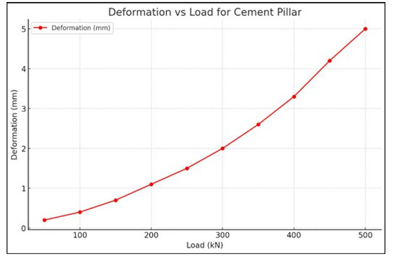
Figure 3: Deformation Versus Load
Discussion
The experiment demonstrated the relationship between the applied load and both the compressive stress and deformation experienced by the cement pillar. As the load increased, both compressive stress and deformation followed an upward trend. The cement pillar withstood incremental increases in load up to 500 kN, at which point it reached its failure point with a compressive stress of 43.8 MPa and a deformation of 5.0 mm. The first plot showed a roughly linear relationship between load and compressive stress, which is typical for cement pillars under compression until they approach failure. The deformation plot indicated a progressively larger deformation as the load increased, especially as the pillar neared failure, suggesting material strain and a nearing structural limit. The cement pillar exhibited a maximum compressive stress of 43.8 MPa before failure. This data provided insights into the pillar’s load-bearing capacity and its deformation behavior under stress,useful for determining structural applications and mix optimization for similar cement pillars. Further studies with variations in pillar dimensions or cement mix might help to improve performance under higher loads.
Conclusion
The experiment concluded that the constructed cement pillar reached its maximum compressive strength at 43.8 MPa, at which point it failed under a load of 500 kN with a deformation of 5.0 mm. The data demonstrated that the pillar’s strength and deformation increased proportionally with the applied load until failure. This behaviour indicated that the cement pillar maintained structural integrity under increasing loads up to its maximum capacity. The findings provided valuable insights into the load-bearing limitations of the pillar, suggesting that similar pillars might require adjustments in composition or dimensions for higher load-bearing applications [19].
References
- M. Neville, "Properties of Concrete," 5th ed., Pearson Education, 2011.
- M. N. Pavlovic, "Concrete Structures," 3rd ed., Springer, 2014.
- American Concrete Institute. (2019). Building code requirements for structural concrete (ACI: 318-19).
- EN 1992-1-1, "Eurocode 2: Design of concrete structures - Part 1-1: General rules and rules for buildings," CEN, 2004.
- A. K. Chopra, "Dynamics of Structures: Theory and Applications to Earthquake Engineering," 5th ed., Pearson Education, 2017.
- Zienkiewicz, R. T. O. C., & Zhu, J. (2013). The Finite Element Method Set. Its Basis and Fundamentals.
- S. S. Rao, "The Finite Element Method in Engineering," 5th ed., Butterworth-Heinemann, 2017.
- ACI, A. (2014). Building Code Requirements for Structural Concrete (ACI 318-14): commentary on building code requirements for structural concrete (ACI 318r-14): an ACI report. American Concrete Institute. ACI.
- ACI Committee 301, "Specifications for Structural Concrete(ACI 301-16)," American Concrete Institute, 2016.
- EN, B. S. (2000). 206-1 Concrete-Part 1: Specification, performance, production and conformity. British Standards Institution.
- ACI Committee 209, "Guide to the Selection and Use of Concrete Mixtures (ACI 209R-18)," American Concrete Institute, 2018.
- ACI Committee 349, "Code Requirements for Nuclear Safety Related Concrete Structures (ACI 349-13)," American Concrete Institute, 2013.
- ACI Committee 224, "Guide to Concrete Repair (ACI 224R- 13)," American Concrete Institute, 2013.
- ACI Committee 222R, "Guide to Concrete Inspection (ACI 222R-19)," American Concrete Institute, 2019.
- American Concrete Institute (ACI) 318-19: Building Code Requirements for Structural Concrete.
- Nehdi, M. L., & Benmokhtar, M. (2003). Bond between steel reinforcement and concrete: State-of-the-art report. ACI Materials Journal, 100(2), 124-141.
- Mehta, P. K., & Monteiro, P. J. (2006). Concrete microstructure, properties, and materials. McGraw-hill.
- ACI Committee 309. (2010). Report on consolidation ofconcrete. ACI Concrete International, 32(10), 53-62.
- ACI Committee 209. (2016). Report on parking structures. ACI Concrete International, 38(1), 43-51.