
AI and Intelligent Systems: Engineering, Medicine & Society(AIISEMS)
ISSN: 3068-9503 | DOI: 10.33140/AIISEMS


Research Article - (2026) Volume 2, Issue 2
Design and Fabrication of a Foot-Operated Steering System for Armless People
Received Date: Mar 06, 2026 / Accepted Date: Apr 08, 2026 / Published Date: Apr 27, 2026
Copyright: ©2026 Ganesh S, et al. This is an open-access article distributed under the terms of the Creative Commons Attribution License, which permits unrestricted use, distribution, and reproduction in any medium, provided the original author and source are credited.
Citation: Ganesh, S., Harishwar, R. G., Amira Carel, A., Janani, S., & Priyadharshini, R. (2026). Design and Fabrication of a Foot-Operated Steering System for Armless People. AI Intell Sys Eng Med Society, 2(2), 01-03.
Abstract
Independent mobility remains a major challenge for individuals with upper-limb disabilities, as conventional vehicle control systems are primarily designed for hand-operated steering and braking. This paper presents the design and development of a foot-operated steering mechanism intended for armless users. The proposed system employs a rack- and-pinion arrangement actuated through a gear-assisted motor and rotary encoder interface, enabling precise steering control using lower-limb motion. A 24 V DC drive system provides propulsion, while braking and acceleration are integrated through dedicated foot controls. Detailed mechanical design calculations, steering geometry analysis, torque estimation, and energy evaluation are presented to validate system feasibility. The prototype demonstrates stable steering response within ±30° lock range and achieves an estimated operational range of 10.8 km under nominal loading conditions. The developed mechanism offers a cost-effective and practical assistive mobility solution that enhances independence and promotes inclusive vehicle design.
Keywords
Assistive Driving Technology, Foot Controlled Steering Mechanism, Rack and Pinion Steering, DC Motor Actuation, Human Machine Interface
Introduction
Personal transportation has become essential for daily commuting, particularly in rapidly urbanizing regions. However, conventional vehicle control systems are primarily designed for individuals with full upper-limb functionality. Persons with upper-limb disabilities encounter significant challenges in operating steering wheels, braking systems, and throttle mechanisms. Existing assistive mobility devices such as wheelchairs and prosthetic aids provide short-distance support but are unsuitable for long-distance independent transportation. Therefore, alternative control strategies utilizing lower-limb strength present a promising solution. This study aims to design and fabricate a cost-effective foot-operated steering mechanism that enables independent vehicle operation using leg movement. The proposed system integrates mechanical steering transmission with embedded electronic control to ensure precision, safety and ergonomic feasibility.
Working of the System
The steering input is provided through a circular foot operated interface. Rotational movement of the foot cap is detected by an incremental rotary encoder, which generates quadrature signals corresponding to angular displacement. The microcontroller processes encoder counts and maps them proportionally to a predefined steering range of ±30°.Based on this computed angle, control signals are sent to a DC worm gear motor. The motor rotates a pinion gear that meshes with a linear rack, converting rotational motion into linear displacement. This displacement alters the angular position of the front wheels via steering linkages. Acceleration and braking are controlled through the left foot using mechanical switches and linkages. Propulsion is provided by a 250 W DC motor powered by two 12 V lead-acid batteries connected in series to provide 24 V. The system operates in a closed loop configuration, ensuring accurate steering alignment and automatic return to neutral position.
CAD Model of the Foot-Operated Steering System
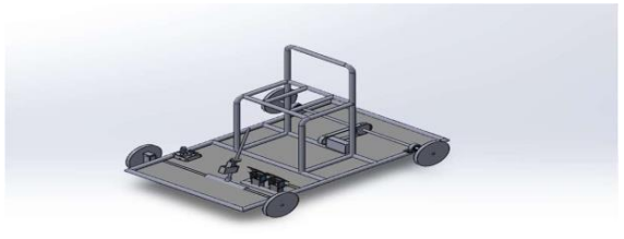
Figure 1: CAD Model of The Foot-Operated Steering System
Electrical Components
The electrical system of the robot consists of 1Arduino uno,1-12v Lead Acid Battery,1-DC gear motor and 1- Encoder.
Arduino UNO R3
The Arduino Uno R3 functions as the primary embedded controller within the steering system. It processes quadrature signals received from the rotary encoder and converts positional data into motor control commands. Using programmed logic developed in the Arduino IDE, the controller regulates steering motor direction and displacement through pulse-width modulation (PWM), enabling proportional steering response.
Lead Acid Battery
The propulsion and control circuitry are powered by two 12 V sealed lead-acid batteries connected in series to provide a 24 V supply. This configuration ensures adequate voltage for the 250 W DC motor while maintaining system simplicity and cost effectiveness. The selected battery capacity supports short-duration operation suitable for prototype validation.
Rotary Encoder
A quadrature incremental rotary encoder is employed to measure angular displacement of the foot operated steering cap. The encoder generates digital pulse signals corresponding to rotational movement, allowing precise computation of steering angle relative to the neutral position. This feedback mechanism enables accurate position-based steering control.
Rack and Pinion Mechanism
The rack-and-pinion assembly translates rotational input from the steering motor into linear displacement of the rack, which in turn adjusts the angular orientation of the front wheels. This configuration ensures direct mechanical linkage, predictable steering geometry and reduced backlash compared to cable-based alternatives.
DC Geared Motor
A 24 V DC worm-gear motor is selected for steering actuation due to its high torque output at reduced speed. The integrated gearbox enhances torque multiplication and provides self-locking characteristics, thereby preventing unintended steering drift when no input is applied.
Design Calculations
Vehicle Load Analysis
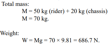
Tractive Force Requirement
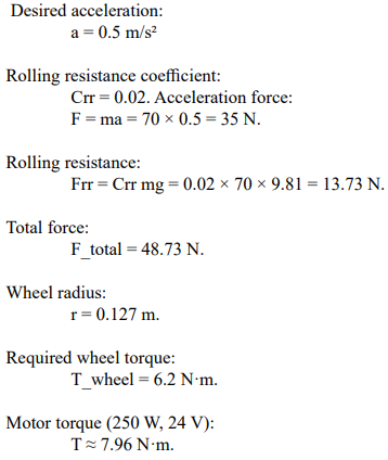
Battery and Range Estimation
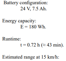
![]()
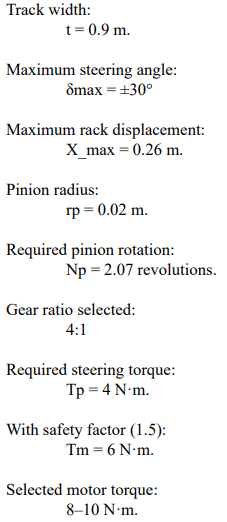
Steering Geometry
Control System and Programming
The steering interface is implemented using an embedded microcontroller platform. The rotary encoder provides real-time angular feedback to the controller. The encoder count C is mapped linearly to steering angle: δ = (C / Cmax) × δmax. A neutral reference is defined during initialization. Deviation from this reference triggers proportional motor actuation. Software-based safety limits restrict steering within ±30°.Closed-loop position control ensures accurate steering response and prevents mechanical overtravel.
Results and Discussion
The fabricated prototype demonstrated stable steering performance with smooth transition between left and right steering limits. The rack-and-pinion mechanism provided responsive wheel deflection with minimal backlash. The propulsion system achieved the expected acceleration under flat-road conditions. Battery endurance testing confirmed approximately 40-45 minutes of continuous operation under nominal load. The steering torque requirement remained within motor capacity limits, validating design calculations.
Future Upgrades
Future enhancements may include:
• Steer-by-wire architecture with redundancy.
• Integration of driver-assist features.
• Regenerative braking.
• Higher capacity lithium battery system.
• Adjustable ergonomic foot interface.
Conclusion
The developed foot-operated steering system provides a practical and economical mobility solution for individuals with upper-limb disabilities. Through mechanical optimization and embedded control integration, the system achieves safe and reliable steering performance within defined limits. The study demonstrates the feasibility of adapting conventional steering principles into assistive vehicle applications, contributing to inclusive automotive engineering [1-11].
References
- Shaik, Z. B., & Peddakrishna, S. (2025). Design and implementation of electric vehicle with autonomous motion and steering control system using single board computer and sensors. Results in Engineering, 25, 103995.
- Bansal, P. (2022). Design and analysis of steering geometry for small electric vehicles. Materials Today: Proceedings, 63, 1245–1251.
- Kumar, R. (2022). Experimental investigation of rack-and-pinion steering system for low-speed electric vehicle. SAE Technical Paper, 2022-01-1123.
- Ramesh, S. (2021). Development of adaptive driving controls for differently abled drivers. International Journal of Vehicle Structures & Systems, 13(1), 45–52.
- Natarajan, S. (2021). Kinematic analysis of steering linkage for electric mobility platform. Materials Today: Proceedings, 45, 6712–6718.
- Patel, R. (2021). Design optimization of DC motor drive system for steering assist applications. International Journal of Power Electronics and Drive Systems, 12(3), 1563–1571.
- Rajamani, R. (2020). Integrated vehicle control for electric vehicles. Vehicle System Dynamics, 58(8), 1123–1145.
- Steering mechanism: Rack and pinion motion and lead screw transfer using C-clamp. (2022). International Journal of Innovative Research in Science, Engineering and Technology, 11(6).
- Bolton, W. (2003). Mechatronics: electronic control systems in mechanical and electrical engineering. Pearson Education.
- Patel, A., Bhatt, N., & Rawade, M. R. (2019). Design methodology and manufacturing of rack and pinion for all terrain vehicle. Int J Eng Res Technol (IJERT), 8, 422-425.
- Kerkar, R., Veer, D., Yadav, S., Yenpure, S., & Deokar, S. B. (2024). Design and optimization of steering system in electric vehicle. Journal of Emerging Technologies and Innovative Research, 11(7), 102.