
Journal of Applied Material Science & Engineering Research(AMSE)
ISSN: 2689-1204 | DOI: 10.33140/AMSE
Impact Factor: 0.98

Research Article - (2025) Volume 9, Issue 2
Damage Identification in Offshore Structures Using Wavelet Transform of Space Domain Signal
Received Date: Feb 23, 2025 / Accepted Date: Jun 14, 2025 / Published Date: Apr 25, 2025
Copyright: ©Ã??Ã?©2025 Samira Mirzavand, et al. This is an open-access article distributed under the terms of the Creative Commons Attribution License, which permits unrestricted use, distribution, and reproduction in any medium, provided the original author and source are credited.
Citation: Ghafouri, H. R., Mirzavand, S. (2025). Damage Identification in Offshore Structures Using Wavelet Transform of Space Domain Signal. J App Mat Sci & Engg Res, 9(2), 01-11.
Abstract
Large structures such as bridges, towers, offshore platforms are designed to be used over a long-time period. How- ever, due to the unpredictable and out-of-control events, structural damages occur prematurely. Poor performance or failure of these structures will lead to irreparable impacts. To avoid these losses, engineers always look for methods to detect damages in structures in early stages of occurrence and to reveal their remaining life at the lowest cost. Thus developing a method for detecting system defects is a vital step. One of the main issues in damage detection methods is to seek some damage indexes that are sensitive to structural damage. In this research, a method is developed based on wavelet transform of structural responses and a good index for damage detection in offshore platforms is proposed. Structural data obtained from modal and time-history analysis of a fixed offshore platform under wave and ocean current loads are used as input data for wavelet analysis. The results of these two analysis after wavelet transform have been compared together, and feasibility of using the displacement of the structure subject to environmental loads as an index to detect damage of the structure using wavelet analysis has been investigated. The results showed that time- history responses are more sensitive to stiffness reduction and has better performance in damage detection than modal response of the first mode of platform.
Keywords
Damage Detection, Structural Health Monitoring, Fixed Offshore Platform, Spatial Wavelet Transform, DWT, SWT
Introduction
Vibration-based damage detection techniques are gaining popularity among researchers due to their non-destructive nature and potential to achieve a continuous structural health monitoring at a low cost [1]. The basic idea of these methods is that fault will alter the stiffness, mass or energy dissipation properties of a system which in turn change the measured dynamic response of the system [2]. Roy and Ray-Chaudhuri stablished a mathematical basis to show the correlation between a structural damage and a change in the fundamental mode shape and its derivatives [1]. They showed that the change in the mode shape and its derivatives are associated with the location of damage. The presence of damage in the structure causes very minor discontinuities in responses of structure. These discontinuities cannot be usually observed in structure response curves; but wavelet transform coefficients properly clarify these discontinuities. Wavelet based approach can provide an alternative to classical approaches in damage detection. Wavelets are usually used to analyze signals in the time domain. However, by replacing time variable t with a spatial coordinate, spatially distributed signals can be analyzes with wavelets [3]. The wavelet coefficients tend to show irregularity near the crack. This property enables one to find the location of damage in the structure [4]. Wu and Wang studied identification of damage in an aluminum cantilever beam in different depths using spatial wavelet transform and Gabor Wavelet Function. Zhong and Oyadiji, in absence of parameters of the original sound structure, presented a method of damage detection in beam-shaped structures with crack ratio of lower than 5% [5,6]. Considering the novelty of wavelet analysis for damage detection, researches have continued use of the method for various engineering applications. The present study aims feasibility of this damage identification method in offshore platforms. This method only needs the spatially distributed signals (the displacements).
Thus far, many researches have been conducted in damage detection of offshore platforms and different methods have been devised. Shahverdi et al. studied damage detection in jacket platforms using Reduced Wavelet Component Energy [7]. They used signals were measured from Finite Element Analysis results under simple wave load then decomposed the results into Wavelet Packet Components and detailed components of signal were calculated and used for damage detection. The best decomposition level was 4. After decomposition of signals, the Detail Signal Energy Rate Index (DSERI) was calculated. They could diagnose damage up to 10% reduction in stiffness very well using this method. Sherafat et al. used wavelet transform of free or ambient vibration responses of structures to damage detection in jacket platforms [8]. The proposed method need 2 stage response of structure: Pre-Damage and probable Post-Damage. Occurrence of damage between these two stages were investigated via the vibration of Damage Locator Index (DLI) along the platform height. Kenna and Basu concentrated their studies on identifying local damage which can occur at an interface connection by either material or bolt/tendon failure of a wind turbin towers using spatial DWT (Discrete Wavelet Transform) of the strain signals and concluded that using spatial DWT of the strain signal could be a powerful means of locating damage at wind turbin tower interface connections [9]. The stiffness connection in this case was 50%. Rahami et al. used recorded Acceleration responses decomposition using Wavelet Packet Transform and the concepts of Energy Entropy and performing a sensitivity analysis to select the damage sensitive components. Investigation by authors shows that 6th level of Wavelet Packet decomposition is the most convenient one to achieve damage sensitive component [10]. Asgarian et al. studied efficiency of using Rate of Signal Energy using Wavelet Packet Transform for damage detection of offshore platforms [11]. They used high frequency signal in time domain. Acceleration Signals as output of sensors located on different levels of platform used for damage diagnosis using rate of signal energy. The dynamic test of scaled model platform was performed using force vibration methods with harmonic excitation across a 0-10 Hz frequency. Shahverdi et al. in another article used DSERI and DWT coefficients to detect damage in subsea free span pipelines [12]. They could detect damage up to 40% stiffness reduction near the supports location with two methods without any effects of boundary conditions on results for the pipeline. DWT in first level of analysis could be able to detect location of damage. But, DSERI at level 2 and 3 detected damage location. It is reasonable to say that less effort in calculation is preferred. In all of these methods, researchers have intended to identify effect of failure on structural parameters of platform to identify the related damage on the platform; therefore, damage identification methods are mostly available as measurement of structural parameters of an original sound platform and comparison with that of present platform under service conditions.
Even though, notable research works have been done in identifying damage in offshore platforms in recent years, but so far, the displacement response of a model subjected to wave, rarely has been used to identifying damage in offshore platforms. In present study, the displacement responses of the finite element model of a fixed offshore platform has been used as the “spatial signal” under study. To simulate the response of the structure in real environmental condition of sea, the platform was analyzed under the loading of sea waves and ocean currents. DWT and SWT (Stationary Wavelet Transform) were used to detection of damage. Damage was detected in the first level of decomposition. Thus, further level of calculation was eliminated. Further more the structural properties of the original sound structure were not required for wavelet analysis. In addition, using space domain and low frequency signal to damage detection make this approach less susceptible to the potential drawback of wavelet transform which is poor performance in high frequencies. For this purpose, finite elements model of a sample representative platform was prepared and then damage was artificially induced at different points of the structure as stiffness reduction in element. The model was analyzed using Finite Element Method (FEM) and the obtained displacements of modal and time-history analysis called spatial signals, were utilized for diagnosing. Then, ability of two approaches under wavelet analysis was investigated for identifying damage location in various members of modeled platform. In the end a comparison was performed between two approaches outputs for stiffness reduction up to 87.5 percent in presence of 10 percent measurement noise.
Fundamentals of Wavelet Analysis
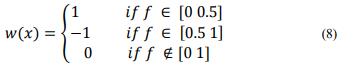
Wavelet functions wa (x) the so-called daughter wavelets, defined as follows:
They are obtained from a function called mother wavelet wx. Each daughter wavelet is created by scaling and transferring mother wavelet where a is symbol of scaling and b is symbol of transfer-
ring mother wavelet function, If function f(x) is a spatial signal, wavelet transform will create a correlation between functions f(x) and wa,b(x), which is defined as a series of coefficients c(a,b). If continuous wavelet transform is used, these coefficients will be ob- tained as summation of product of function (x) and the scaled and transferred mother wavelet function. This has been shown in Eq. 2.

As scale parameter of a becomes smaller, the wavelet function becomes more compressed, and it oscillates faster, which is an indication of higher frequencies. When the scale parameter of a is become larger, the wave becomes more expanded and oscillates more slowly and in a longer period of space, and this is an indication of lower frequencies. Therefore, this method analyzes the signal in different frequencies with different magnifications.
Discrete Wavelet Transform (DWT)
Discrete wavelet transform (DWT) is another form of wavelet transform that is used in signal analyzing. In DWT a and b are defined as follows:
a=2-j, b= 2-jk
Where j is the level of decomposition and k is time or space position, and wj (x) is defined as follow
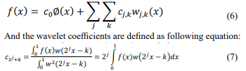
Where Ø(x) is defined as the scale function the summation of the terms that are in the form of relationship 4 make the wavelet expansion of the function f(x):
In theory, the wavelet transform of a signal can be continued up to infinite levels (j → ∞), but the number of the levels of the wavelet transform depends on the type of analysis and the need that we have for the extraction of different frequencies from the signal. [14].
From equation 5, we can also conclude that wavelet transform co- efficients are a function of scale and location.
For the DWT special families of wavelet functions are developed. Some generally used families for the DWT are shown hereby their wavelet functions.
Daubechies
The Daubechies family is named after Ingrid Daubechies who invented the compactly supported orthonormal wavelet, making wavelet analysis in discrete time possible. The first order Daubechies wavelet that is also known as the Haar wavelet can be written as:
Coiflets
Coiflets are also built by I. Daubechies on the request of R. Coifman. Coifman wavelets are orthogonal compactly supported wavelets with the highest number of vanishing moments for both the wavelet and scaling function for a given support width. The Coiflet wavelets are more symmetric and have more vanishing moments than the Daubechies wavelets.
Symlets
Symlets are also orthogonal and compactly supported wavelets, which are proposed as modifications to the Daubechies family. Symlets are near symmetric and have the least asymmetry. The properties of symlets are nearly the same as those of the db wavelets.
Biorthogonal
A biorthogonal wavelet is a wavelet where the associated wavelet transform is invertible but not necessarily orthogonal. In the biorthogonal case, there are two scaling functions Ø, Ø, which may generate different multiresolution analyses, and accordingly two different wavelet functions w, w.
Stationary Wavelet Transform (SWT)
Stationary Wavelet Transform (SWT) is an extension of the standard discrete wavelet transform. Stationary wavelet transform uses high and low pass filters. SWT apply high and low pass filters to the data at each level and at next stage produces two sequences. The two new sequences are having same length as that of the original sequence
In this research, wavelet coefficients in the first level of decompo- sition was used for damage detection.
Result of this conversion is wavelet coefficients, which indicate extent of correlation between wavelet function wa,b (x) and function f(x). Where f(x) is the deflection of a beam at coordinate of x, If there is a discontinuity or a sharp peak in function f (x) , wavelet coefficient C(a, b) at the same corresponding point has a large amplitude too. This is the main idea behind wavelet transform for determining damage in structure. Studying these coefficients helps in finding accurate location of discontinuities in input spatial signal which are, in fact, the damaged locations in the structure.
Analysis Steps
Damage detection method in the structure using wavelet coefficients can be described step by step as follows:
1. The desired signal is first measured. This signal can be computed from a numerical model or measured by installing precise and sensitive sensors on the desired structure. In this research, the sought signals, computed from numerical models, were displacements of structure under environmental condition. In the numerical model, failure was modeled as reduction of elasticity modulus of some elements. In this study only the first mode of deformation was considered and the higher modes were ignored.
2. The next step is selection of suitable mother wavelet for the desired conversion. One of the most important problems for using wavelet transform is allocation of a suitable wavelet for analysis. Investigating different wavelets in several scales and analyzing levels, demonstrates that wavelets db, coif, and sym are useful for damage detection [15].
3. Having determined the input signals and a suitable wavelet, detail coefficients cj , are obtained using equation (2).
4. The detail coefficients are drawn and analyzed. The details coefficients demonstrate hidden details in signal.
5. Calculation rate is specified at different levels depending on the damage type, input signal, general specifications of structure and problem type. The calculations level which should be done for each problem can be determined and this depends on precision and type of problem and the response which is expected from the problem. In this research, damage was detected in the first level of decomposition and further calculation was not necessary. The lower decomposition level which can correctly identify the damage location is important since the lower decomposition level will reduce the computation efforts [15].
In the following sections a simple test case is provided first. This is just to show the applicability of the proposed method. It is done using the same step-by-step method described above. Then a more comprehensive example is given.
Example 1: A Simple Beam
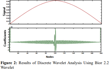
To prove applicability of this method, it was verified against a simple beam. Specifications of the modeled beam are as follows: Length: L = 200cm, width: B = 10cm, height: h= 20cm, Density : 7850 kg⁄m3 , modulus of elasticity : E = 2.1 × 10¹¹ N⁄m3 , Poisson ratio: v = 0.3
The beam was modeled using 200 equally- spaced elements, each 1 cm in length
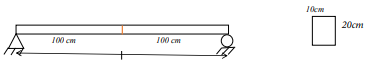
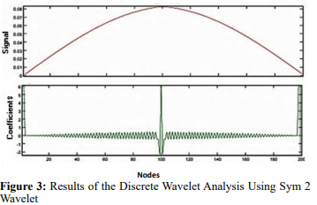
In this beam, an artificial failure was created in the mid-span by 10% decreasing stiffness of the respective element. After perform- ing structural analysis, the obtained displacements of the damaged beam was considered as spatial signal f (x). Both original and dam- aged beam curves are given in Figure1 for comparison
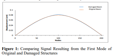
Displacement of the first mode of damaged beam which is an input signal for wavelet analysis is illustrated in Figure 1. As shown, the damaged location is hardly identifiable in the beam's displacement diagram. To perform wavelet analysis on structure displacements curve, 201 nodal displacements resulting from modal analysis were extracted and defined as an input signal. It is in fact approximation of a continuous spatial signal with a discrete signal. Then, the resulting signal undertook wavelet analysis with different wavelet functions. Results are shown in Figure 2 and 3. It might be observed that the damage location is very well identified in form of a sharp peak in the resulted wavelet curve
Example 2: Offshore Platform
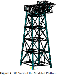
The platform under consideration consists of a jacket with 4 legs and horizontal braces in 5 levels. The structure is 1240 tons in weight and 72.7 m in height. The 3-story deck of the platform, which weighs 1050 tons, was completely modeled in the software. Depth of water in the platform construction site is 66.8 m. In order to analyze the platform and obtain respective data, modeling was carried out in a finite element software. All Elements and sections of the deck and jacket were modeled.
Pipe elements were used for modeling jacket and the deck was modeled using Beam elements with 6 degrees of freedom includ- ing bending, torsion and lateral forces. Self-weight of the struc- ture was calculated by the software. Weight of other parts such as piping, mechanical equipment, cables and electrical equipment and reservoirs were also taken into account by separately applying coefficients to the weight of deck and jacket. The wave load ap- plied to the pipe by the hydrodynamic effects is computed from a generalized Morison’s equation. The wave input using stokes fifth order wave theory and the regional wave information of Persian Gulf with 100-year return period was used. The wave height of
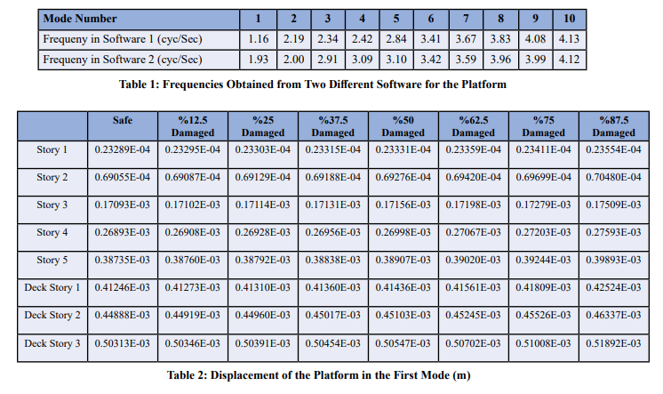
In the first step, modal analysis was carried out on the structure which natural frequencies were obtained. These are shown in table 1 for the first 10 modes.
In absence of validated experimental data, verification of simulated model is considered with adding comparison between frequencies of Jacket in this model (Software 1 in table1) with results of the same simulated Jacket in other software (Software 2). It shows that the natural frequency of model in two software are in the same range. In addition, the modal displacement of the platform for the first vibration mode in safe and damaged condition provided in table 2. The displacement response of the platform increase with increasing the damage percentage of the leg member. Moreover, the results of damaged and undamaged structure from one simulated model have been used in this study. Thus, regarding or disregarding any condition in simulated model have the same effect on both damaged and undamaged cases.
Spatial signal (displacement of different nodes in the studied area) is determined after analyzing structure. The signal would undergo wavelet transform and wavelet coefficients are calculated. Finally, damage location in wavelet diagram is manifested as a large discontinuity in the curve.
Failure Scenario 1
For the first step, failure artificially induced in foremost left leg of jacket (Figure 5). Damage scenarios are introduced by stiffness reduction in elements of model. For this purpose, percentage damage parameter D is defined as below: [17]


As shown in the figure, there is a jump between nodes 21 and 22 where the artificial failure is located. In addition, there is also one jump in the support which is not related to structural failure.
Herein, the previous stages repeated for Y-displacements. Displacements of nodes in Y- direction were assumed as input signal for wavelet analysis. Figures 7 show wavelet transform of signal under different wavelets.
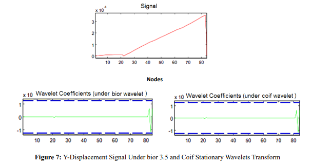
As given in the figures 7, there was a jump in diagram which indicated the damage location between nodes 21 and 22.
In the next stage, the same analysis was carried out for Z-displacement of platform. Figures 8 demonstrate results of wavelet analysis for Z-displacement signal. There was a jump in diagrams between nodes 21 and 22, which was the failure location of the structure.
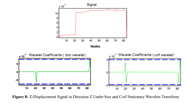
It can be concluded thus far that use of Z-displacement could result in better results in terms of recognizing damage location in legs of jacket platform.
Failure Scenario 2
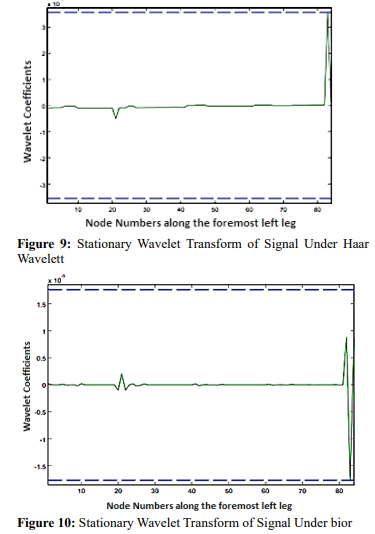
In case an element is highly damaged, as with scenario 1, failure might be monitored even without using wavelet analysis. However, in early stages of failure development it is hardly recognizable. Hence, the robustness of a damage detection method should be tested in recognizing a failure in its early development stages. In such a case, structure's displacements diagram does not experience discontinuities and sudden changes. Therefore, failure cannot be recognized only with structure displacements diagram (signal of the recorded data). Under such conditions, use of wavelet can more effectively detect minor failure location in the structure. For this purpose, an element with minor failure was used. In this example, response of structure was studied while assuming element stiffness reduction 20%. Results of Z- displacement signal wavelet analysis are shown in Figures 9 to 11 for different wavelets. As can be observed, there was jump in accurate location of failure.

Failure Scenario 3
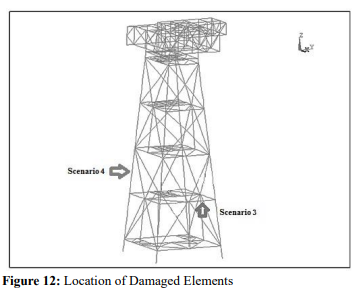
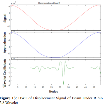
Although Z-direction had better results for leg members of jacket, it was not right about other members of platform. For example in brace members and beam members total displacement and y-direction displacement had best results, respectively. In Scenario 3 two damaged element was simulated between nodes 17, 18 and 31, 32 of a beam member on the second story the time-history analysis of the structure under wave and ocean current loads was used in this scenario. The period of wave was 11 seconds. Therefore, the 11 interval was used for analysis and the response of platform in 11th interval was used as spatial signal to calculations of wavelet coefficients. In the following figure 13 result of wavelet transform is showed. Location of damaged elements are shown in figure 12.
Failure Scenario 4
In this scenario a comparison has been done between stiffness reduction from 0 to 87.5 percent for an element between node 22 and 23 and two other points with change in geometry between nodes 10, 11 and 30, 31. Three elements was determined along the leg member. The purpose is investigation of the sensitivity of this method to change in cross section in joint location comparing to damage location. For cases with 50 to 87.5 percent stiffness reduction an uncertainty is considered in the measurement system too. This uncertainty is because of the noise and measurement error. Although, mentioned uncertainty is minimized recently with the progress of technology and measurement equipment. However, considering this uncertainty is necessary for the exact diagnosis of damage location. The following equation is used for adding measurement uncertainty to the extracted features.
fnoisy = fne(1 + uα)
Where f net is extracted features (node location) of the proposed model, u is a random number in the interval [-0.01, 0.01] and α is a noise level parameter [18].
To investigate the effect of measurement noise on results, 10% noise is imposed on the measured signal of the leg member. In addition, number of nodes were decreased to 41 nodes. Figures 14, 15 show the results for Z-displacement signal of leg member with different stiffness reduction in an element between node 22 and 23 and changes in geometry at the points between nodes 10, 11 and 30, 31 in presence of 10% noise.
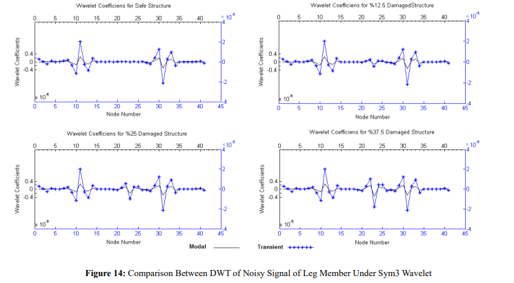
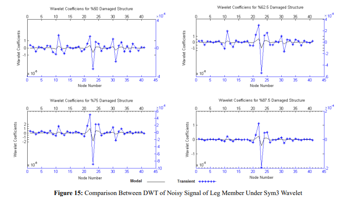
In comparison, although the location of damaged element is visible with good accuracy in leg member for results of time-history analysis, it was not good enough about modal analysis results. It can be therefore concluded that spatial signal derived from modal analysis is less sensitive for damage detection than signal obtained from time-history analysis and displacement signal gained from time-history analysis under environmental loads is a better index for damage detection in offshore platforms.
This method is very sensitive to stiffness changes. Therefore, use of this method in support area and joint of different members in structure maybe potentially companion with inaccuracy. But, results shows that for reduction in stiffness up to 37.5 percent this method is more sensitive to change in stiffness because of change in geometry and for stiffness reduction higher than 50 percent jump in location of damaged element has more higher quantity than jump in locations of geometry changes. Therefor this approach is more accurate for damages with stiffness reduction more than 50 percent.
In addition, in presence of 10 percent noise the result of time-history analysis can still show the location of damage with good accuracy. Thus this approach is robust against measurement noise for more than 50 percent damages.
Conclusion
In this paper, using Space Domain Signal obtained from time-history and modal analysis has been used for damage detection in fixed offshore platforms using wavelet coefficients. In this regard, measured displacement of a finite element model of a platform for fixed-based condition has been used to investigate efficiency of proposed method to apply in fixed offshore platforms. This method was implemented for stiffness reduction from 12.5 to 87.5 percent and properly specifies damage location.
Considering the research conducted herein, displacement response of structure under environmental condition and wavelet coefficient was proposed as an index for damage detection of jacket type off- shore platforms. Time-history analysis response of the structure is more sensitive than the Modal response of the structure in both cases of geometry change and stiffness change. SWT and DWT showed a good performance in detection of damage. They could detect the location of damage in the first decomposition level. Also, in addition to previously mentioned wavelets, wavelet rbio had good performance in damage detection.
Furthermore, using Z-direction responses for leg members resulted in better damage identification outputs. However, total displace- ment of x, y and z direction as an input signal for wavelet analysis yielded the best answers in brace members and Y-direction had better results for beam members of fixed jacket platform.
In addition, the proposed method is more sensitive to stiffness re- duction and has higher performance than traditional modal method in damage detection. This method is robust to the measurement noise [1-18].
References
- Roy, K., & Ray-Chaudhuri, S. (2013). Fundamental mode shape and its derivatives in structural damage localization. Journal of Sound and Vibration, 332(21), 5584-5593.
- Yam, L. H., Yan, Y. J., & Wei, Z. (2004). Vibration-based non destructive structural damage detection. Key Engineering Ma- terials, 270, 1446-1453.
- Chang, C. C., & Chen, L. W. (2004). Damage detection of a rectangular plate by spatial wavelet based approach. Applied Acoustics, 65(8), 819-832.
- Kim, H., & Melhem, H. (2004). Damage detection of struc- tures by wavelet analysis. Engineering structures, 26(3), 347- 362.
- Wu, N., & Wang, Q. (2011). Experimental studies on damage detection of beam structures with wavelet transform. Interna- tional Journal of Engineering Science, 49(3), 253-261.
- Zhong, S., & Oyadiji, S. O. (2011). Detection of cracks in simply-supported beams by continuous wavelet transform of reconstructed modal data. Computers & structures, 89(1-2), 127-148.
- Shahverdi, S., Lotfollahi-Yaghin, M. A., & Asgarian, B. (2013). Reduced wavelet component energy-based approach for damage detection of jacket type offshore platform. Smart structures and systems, 11(6), 589-604.
- Sherafat, Z., Asaee, Z., Anvar, S. A. (2014). DAMAGE DE- TECTION OF FIXED JACKET OFFSHORE PLATFORMS FROM AMBIENT VIBRATIONS USING WAVELET TRANSFORM.
- Kenna, A., & Basu, B. (2015, July). Damage detection in wind turbine towers using a finite element model and discrete wave- let transform of strain signals. In Journal of Physics: Confer- ence Series (Vol. 628, No. 1, p. 012067). IOP Publishing.
- Rahami, H., Tehrani, H. A., Akhavat, M., & Amiri, G. R. G. (2016). Damage detection in offshore fixed platforms using concepts of energy entropy in wavelet packet transform. Amirkabir Journal of Civil Engineering, 48(3), 241-248.
- Asgarian, B., Aghaeidoost, V., & Shokrgozar, H. R. (2016). Damage detection of jacket type offshore platforms using rate of signal energy using wavelet packet transform. Marine Structures, 45, 1-21.
- Shahverdi, S., Lotfollahi-Yaghin, M. A., & Shahverdi, M. (2013). Subsea free span pipeline damage detection based on wavelet transform under environmental load. Persian Gulf Scientific Research Journal, 4(12), 51-64.
- Rioul, O., & Vetterli, M. (1991). Wavelets and signal process- ing. IEEE signal processing magazine, 8(4), 14-38.
- Mertins, A., & Mertins, D. A. (1999). Signal analysis: wave- lets, filter banks, time-frequency transforms and applications. John Wiley & Sons, Inc..
- Lotfollahi-Yaghin, M. A., Shahverdi, S., Tarinejad, R., & Asgarian, B. (2011, January). Structural health monitoring (SHM) of offshore jacket platforms. In International Con- ference on Offshore Mechanics and Arctic Engineering (Vol. 44335, pp. 579-588).
- Asgarian, B., Shokrgozar, H. R., Shahcheraghi, D., & Ghase- mzadeh, H. (2012). Effect of soil pile structure interaction on dynamic characteristics of jacket type offshore platforms. Coupled Syst Mech, 1(4), 381-395.
- Mojtahedi, A., Yaghin, M. L., Hassanzadeh, Y., Ettefagh, M. M., Aminfar, M. H., & Aghdam, A. B. (2011). Developing a robust SHM method for offshore jacket platform using model updating and fuzzy logic system. Applied Ocean Research, 33(4), 398-411.
- Aqdam, H. R., Ettefagh, M. M., & Hassannejad, R. (2018). Health monitoring of mooring lines in floating structures us- ing artificial neural networks. Ocean Engineering, 164, 284- 297.