

Journal of Sensor Networks and Data Communications(JSNDC)
ISSN: 2994-6433 | DOI: 10.33140/JSNDC
Impact Factor: 0.98


Research Article - (2026) Volume 6, Issue 1
Compensation of Beam Divergence Effects in Multimodal Sensor Fusion
Received Date: Jan 20, 2026 / Accepted Date: Feb 27, 2026 / Published Date: Mar 19, 2026
Copyright: ©2026 Greg Passmore. This is an open-access article distributed under the terms of the Creative Commons Attribution License, which permits unrestricted use, distribution, and reproduction in any medium, provided the original author and source are credited.
Citation: Passmore, G. (2026). Compensation of Beam Divergence Effects in Multimodal Sensor Fusion. J Sen Net Data Comm, 6(1), 01-38.
Abstract
Misalignment among optical, infrared, LiDAR, and radar systems arises from fundamental differences in their sampling geometries and divergence characteristics rather than from calibration error. Each modality observes the environment through a distinct sampling function: passive systems integrate radiance over an angular cone, while active systems record discrete returns from narrow beams. As range increases, these differences produce nonlinear distortions, occlusion inconsistencies, and radiometric bias that cannot be resolved through geometric registration alone. This paper formalizes the physical basis of divergence- induced misalignment and introduces a unified correction framework implemented through the Vossel-Aligned Spatial Lattice (VASL). VASL embeds all sensor data within a volumetric lattice where divergence, incidence angle, and occlusion are locally compensated through range-aware kernels and uncertainty propagation. The method includes equirectangular reprojection, anisotropic footprint modeling, occlusion-aware radiometric fusion, and visibility weighting. This unified framework corrects divergence and material interaction effects across active and passive domains, enabling coherent multimodal alignment for analytical fusion and machine learning applications.
Keywords
Multimodal Sensor Fusion, Beam Divergence Correction, Volumetric Alignment, LiDAR–Radar Optical Integration, Radiometric Compensation, Occlusion Modeling, Vossel-Aligned Spatial Lattice (VASL), Range-Dependent Distortion, Anisotropic Footprint Modeling, Geometric Registration Refinement
Introduction
Accurate alignment across optical, infrared, LiDAR, and radar systems requires explicit modeling of how each sensor samples and represents its surrounding environment. The observed disparities are not the result of calibration error or georectification mismatch, but originate in the fundamental physics of beam divergence, aperture geometry, and sampling function. Passive optical and infrared systems integrate radiance over broad angular fields, while active systems such as LiDAR and radar measure pointwise returns constrained by beam width and pulse timing. When these inherently different datasets are projected into a shared spatial frame, range-dependent divergence causes nonlinear spatial distortions, shadowing mismatches, and radiometric inconsistencies. These errors compound with distance and viewing geometry, creating systematic fusion errors that cannot be mitigated through image registration or sensor calibration alone. The Vossel-Aligned Spatial Lattice (VASL) presented here provides a physically grounded solution by embedding multimodal sensor data into a unified volumetric structure that compensates for divergence and occlusion through explicit modeling of beam geometry, material interaction, and radiometric spread.
Physical Basis of Divergence Disparity
Active and passive systems differ fundamentally in how they collect and interpret energy. A LiDAR or radar system emits a narrow, collimated beam, sampling discrete spatial points, whereas an optical or infrared camera integrates radiance over a cone of rays defined by its aperture. Each optical pixel represents an area-weighted average of radiance, while each LiDAR point corresponds to a sharply defined intersection between a single ray and a surface. For fixed angular sampling, the linear footprint increases proportionally with range (∝ r), and the footprint area increases with the square of range (∝ r2). Because the divergence angle remains constant with range, the spot size expands linearly according to
d = 2r tan(θ/2)
In radar, the beamwidth defines azimuthal resolution, while range resolution is determined by the signal bandwidth, Δ r ≈ c / (2B). For unmodulated pulses, B ≈1/τ, so both bandwidth and pulse width affect the effective footprint and its growth with distance. The resulting sampling functions are geometrically and radiometrically noncongruent across modalities.
In optical imaging, the per-pixel angular sampling θ ≈ p / f depends on pixel pitch p and focal length f. The aperture diameter controls diffraction and irradiance but not field of view.
In contrast, LiDAR and radar systems maintain a fixed divergence angle that is typically small. Consequently, the spatial resolution mismatch between active and passive sensors increases approximately linearly with range.
Manifestations of Range-Dependent Distortion
When these datasets are combined, differences in divergence and aperture geometry produce nonlinear spatial distortions. Optical imagery exhibits apparent dilation due to the widening of its sampling cone, while LiDAR and radar preserve angular fidelity. The resulting misalignment increases with range and varies with surface orientation. In LiDAR–optical fusion, it manifests as range-dependent parallax; in radar–optical fusion, it appears as layover, foreshortening, and azimuthal skew arising from oblique wave incidence and differential path length. These distortions cannot be removed by global scaling or affine correction since they vary continuously across the scene and depend jointly on range, wavelength, and geometry.
Occlusion and Material Interaction
Each sensing modality interacts differently with physical materials. Visible light is strongly attenuated by occlusions, while near-infrared and radio-frequency signals penetrate vegetation, dust, and thin materials to varying degrees depending on wavelength and scattering regime. As a result, each sensor measures a slightly different effective surface within the same scene. LiDAR returns may originate beneath foliage where optical imagery records only canopy reflection, while radar, with a longer wavelength, may detect structures entirely hidden in both optical and LiDAR domains. These differences introduce edge inconsistencies, apparent transparency, and halo artifacts where one sensor penetrates and another does not. Occlusion modeling is therefore an inherent component of alignment correction, as each sensor observes a distinct effective surface modulated by wavelength-dependent penetration.
Terminology and Related Work
The divergence and field-of-view disparities described here are discussed across literature under several overlapping terms, including beam divergence mismatch, field-of-view disparity, and radiometric–geometric coupling [1-3]. For example, the divergence of laser beams in LiDAR introduces measurement uncertainty that must be considered in LiDAR–camera calibration workflows [1]. Field-of-view disparity is addressed in small-FoV LiDAR–camera systems that exhibit limited angular overlap [2]. Radiometric–geometric coupling, though less explicitly named, is implied in LiDAR-optical fusion studies through the joint dependence of reflectance and return intensity on geometry and wavelength [3].
In radar–optical and radar–LiDAR registration, related distortions are described as incidence-angle-dependent projection error, range migration, or layover distortion. Geometric deformations induced by slant-range geometry and variable incidence angle—foreshortening, layover, and shadow—are well documented in SAR image geocoding [4-6]. Range migration is recognized as a geometric distortion in synthetic aperture radar image formation, particularly when large squint angles or wide swaths are employed [7]. These phenomena collectively form a broader class of range-dependent beam divergence disparity, encompassing all cases where differing aperture geometry or wavelength-dependent sampling functions yield spatially misaligned observations.
These range-dependent artifacts have been examined in active–passive calibration, synthetic aperture processing, and hyperspectral–LiDAR fusion, each recognizing that wavelength and geometry jointly determine the effective observed surface [8,9].
The Vossel Concept
A vossel, short for volumetric voxel with spatial lattice alignment, is the fundamental element of the Vossel-Aligned Spatial Lattice (VASL). Each vossel represents a bounded volumetric cell within a common three-dimensional reference frame that integrates data from optical, infrared, LiDAR, and radar systems. Unlike conventional voxels that store scalar quantities such as intensity or occupancy, a vossel encodes directional and radiometric information— specifically, the local incidence vector, divergence angle, and wavelength-dependent reflectance. This structure enables active and passive measurements to coexist within a unified spatial volume, where their differences in sampling geometry and penetration are explicitly modeled. The lattice formed by these vossels provides a continuous, physically grounded medium for evaluating photometric correspondence, range-dependent uncertainty, and occlusion consistency, allowing alignment that remains both radiometrically coherent and geometrically faithful across sensing modalities [10].
Advantages of the Vossel Framework
Traditional alignment strategies between optical, LiDAR, and radar data attempt to compensate for divergence and occlusion through reprojection or learned deformation models. These methods address isolated aspects of the problem but remain limited by their reliance on two-dimensional projections or globally parameterized correction fields. The Vossel-Aligned Spatial Lattice (VASL) extends these approaches by embedding all sensor data directly into a unified volumetric reference frame, where geometric, radiometric, and occlusion effects are reconciled at the voxel—or vossel —level.
Unlike reprojection-based registration, which assumes planar continuity, VASL preserves the full three-dimensional topology of the scene. Each vossel maintains a record of incidence direction, local divergence angle, and wavelength-dependent reflectance, enabling alignment to occur within the physical volume rather than on its image projection. This structure allows divergence correction and radiometric normalization to be applied locally, with range-dependent uncertainty naturally encoded in the lattice density.
By evaluating photometric correspondence within this volumetric framework, VASL maintains angular fidelity and accommodates partial occlusion, shadowing, and penetration differences that conventional methods treat as noise. The selection of photometric centers based on spatial proximity within the vossel grid provides a physically grounded basis for multimodal data association. This approach yields improved coherence across modalities, consistent depth-aware registration, and a measurable reduction in range-dependent alignment error.
Physical Reprojection and Error Propagation
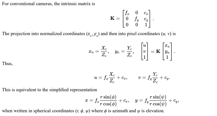
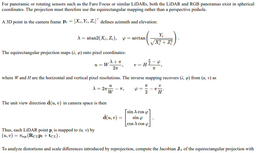
Physical reprojection establishes a geometric mapping from each active sensor measurement (LiDAR or radar) into the coordinate system of the optical or radiometric sensor. This section expands the basic projection model to a full derivation that incorporates intrinsic calibration, extrinsic alignment, equirectangular mapping for 360° systems, and range-dependent error propagation. The objective is to express every LiDAR or radar return as a point in the optical image plane, yielding per-pixel correspondence for cross-modality registration.
Because each Vossel stores both the 3D position and corresponding equirectangular pixel coordinates, the reprojection is inherently invertible. This dual indexing provides a unified spatial key for multimodal fusion without loss of angular fidelity.
Coordinate Systems and Calibration
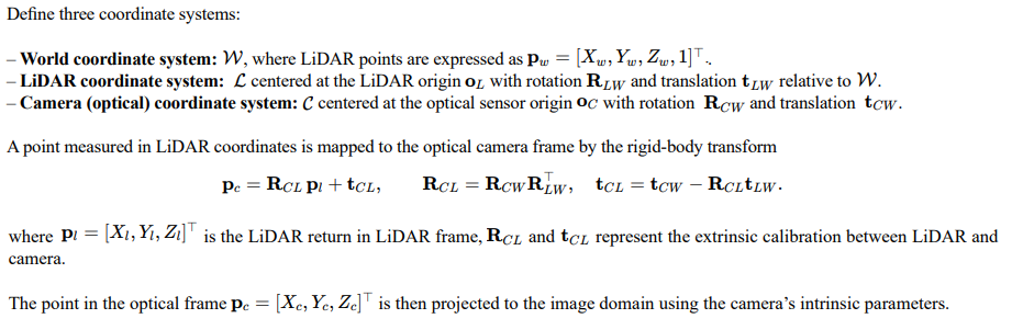
These coordinate relationships define the physical basis for mapping between active and passive modalities, ensuring that each measurement preserves its true spatial correspondence before radiometric or volumetric fusion.
Pinhole Projection Model
Spherical and Equirectangular Projection for 360° Systems
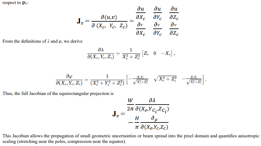
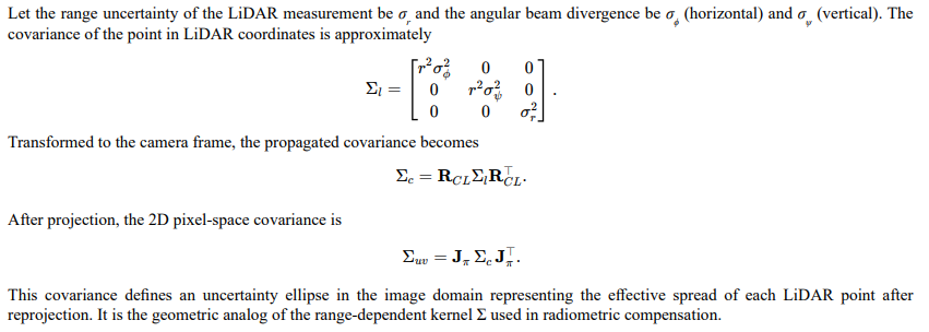
Range Propagation and Uncertainty Ellipsoids
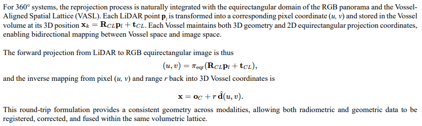
Inverse Projection and Round-Trip Consistency

over all matched LiDAR–camera correspondences yields refined extrinsic parameters. This round-trip constraint ensures geometric closure across transformations, allowing residuals to be interpreted directly as calibration bias or time synchronization error.
Pixel-Integrated Radiometric Mapping

Integration with the Equirectangular VASL Framework
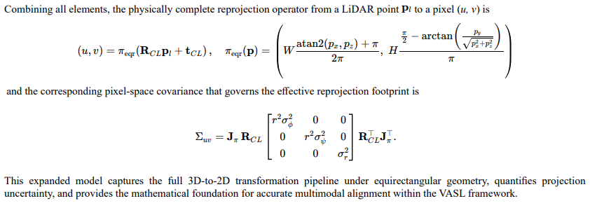
Compact Summary Expression
Range-Dependent Radiometric Compensation
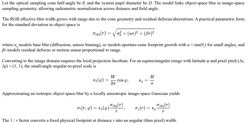
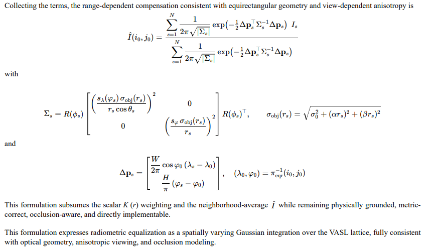
This section expands the range-compensation model to include physically motivated point-spread functions, anisotropy from view geometry, equirectangular metric factors, multiscan fusion, and channel-wise radiometry. The goal is to equalize the effective footprint of RGB measurements with respect to narrow-beam active sensors across range while preserving energy and minimizing bias.
Physical Point-Spread Model
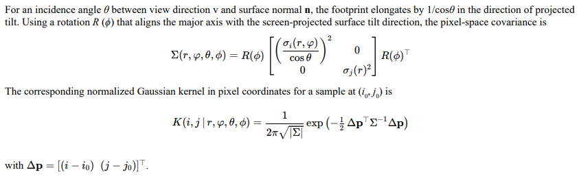
Elliptical Kernel with View-Incidence Anisotropy
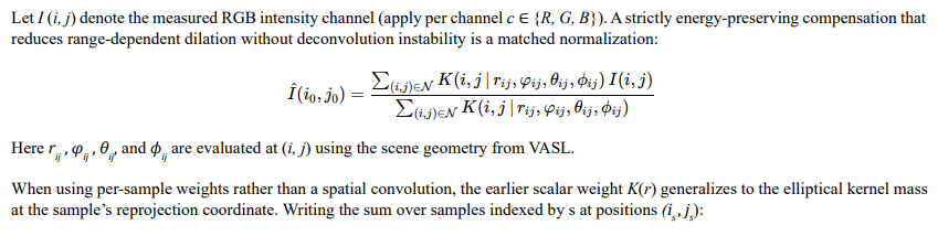
Energy-Preserving Compensation by Matched Filtering
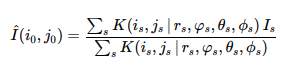
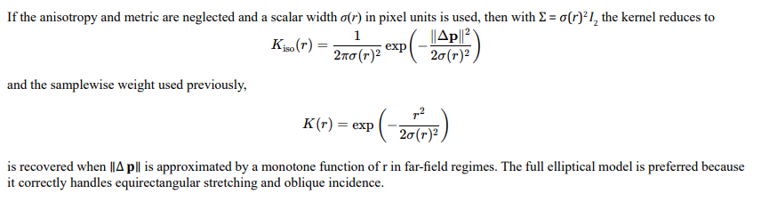
Relation to the Isotropic Scalar Model
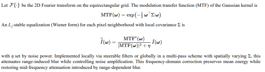
Frequency-Domain View and MTF Equalization
Multiscan and Multimodal Fusion

Coupling to VASL Geometry and Occlusion


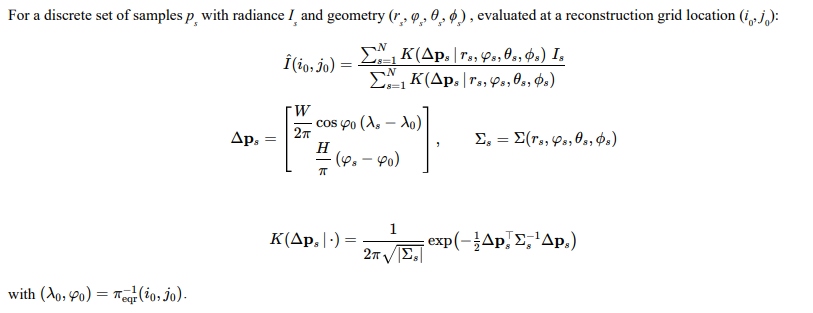
Explicit Sigma Forms over Discrete Samples
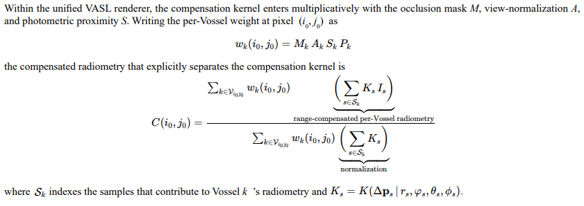
Coupling to the Master Rendering Weights
Parameter Calibration and Identifiability

3.12. Bias and Variance Behavior

Compact Summary of Range-Dependent Compensation
Learned Alignment Fields
Machine learning approaches address nonuniform distortions through learned displacement fields. Neural alignment networks generate dense deformation maps that minimize multimodal misregistration. These methods capture nonlinear distortions introduced by divergence and incidence angle variations but require large datasets and may overfit when visibility conditions differ strongly between sensors.
Radiometric Visibility Mapping Across Views
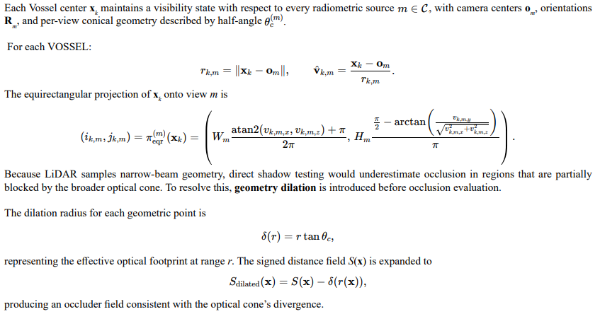
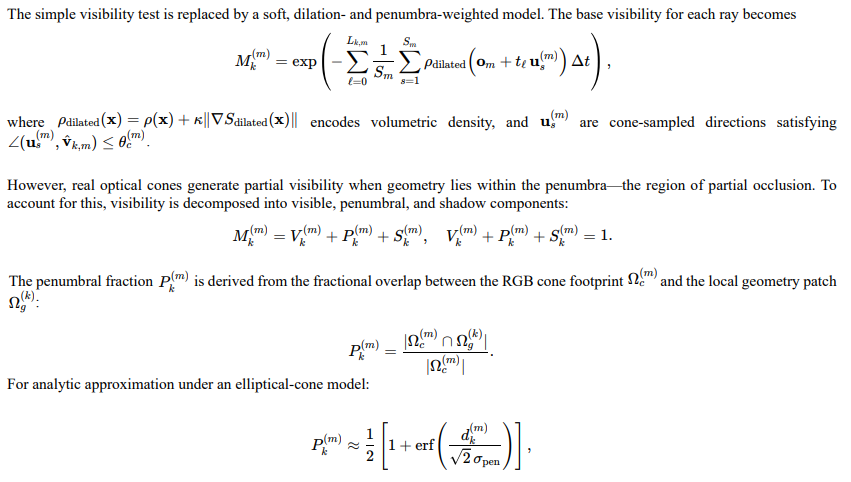
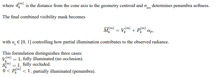
This section extends the occlusion-aware correction model to include distance-based geometry dilation and penumbra modeling for RGB cone intersections. The purpose is to maintain a visibility-aware radiometric record across all sensors that accounts not only for occlusion and range effects but also for partial illumination in penumbral regions. Each Vossel thus represents a persistent radiometric cell that encodes both full and fractional visibility contributions, allowing consistent multi-view color fusion and later recalibration.
Viewwise Visibility Tracking
Dilation- and Penumbra-Aware Visibility Masks
Radiometric Contribution Tensor

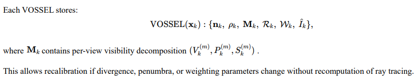
Persistent VOSSEL Radiometric Record
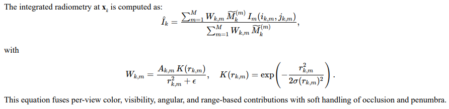
Radiometric Integration Over Views
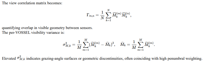
Shadow-State Matrix and View Correlation

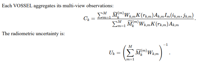
Joint Radiometric–Geometric Accumulation
Tensor Form for Efficient Implementation

Persistent Record and Reintegrability
Each VOSSEL retains visibility, radiometric, and weighting records for all views, ensuring that recalibration or weighting adjustment can be performed without recomputation of occlusion geometry.
Shadowed regions preserve their prior visibility states, while penumbral regions retain their fractional overlap data. This continuity supports progressive refinement and distance-based re-estimation as improved divergence or illumination models are introduced.
The resulting radiometric visibility lattice combines dilation-aware geometry with penumbra-aware radiometry, producing a consistent, physically valid foundation for multi-view fusion across optical, infrared, and active sensing systems.
Integration into the VASL Framework
VASL incorporates elements of all four corrective methods but removes the reliance on planar projections. All measurements are stored volumetrically within the Vossel-Aligned Spatial Lattice, where each Vossel represents a physical region rather than an image coordinate. Reprojection becomes implicit: instead of warping the data to fit a camera plane, VASL positions all samples according to their true three-dimensional origins and observation vectors. Range-dependent compensation is performed locally through divergence-weighted fusion within each Vossel. Learned alignment can still be applied but acts as a refinement step rather than the primary geometric correction.
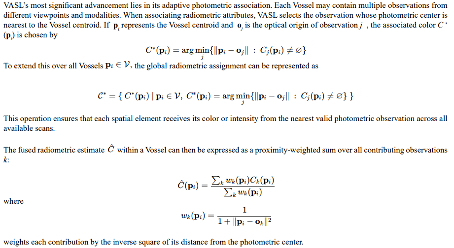
Photometric Center Evaluation
Distortion Avoidance
By fusing sensor data directly within a volumetric structure, VASL avoids the cumulative distortions of reprojection, the incomplete coverage of kernel-based correction, and the instability of unconstrained learned fields. Each Vossel stores spatial, radiometric, and divergence information, allowing deferred projection into any coordinate frame after fusion. Occluded samples can still contribute to local radiometric estimation when visible from alternative viewpoints, maintaining complete spatial coverage.
View-Dependent Projection of RGB Sampling Cones
In addition to the above issues, a significant limitation in colorimetric and radiometric normalization across multiple scan positions arises from the view-dependent geometry of the RGB sensor’s sampling cone. Each pixel of an optical system represents a conical bundle of rays extending from the aperture through the image plane into three-dimensional space. When this cone intersects a surface orthogonally, the projected footprint is circular and uniform. However, when the same cone strikes a surface at an oblique angle, its projection becomes elliptical, and the surface area contributing to the measured color expands in one dimension while compressing in another.
This projection geometry can be described by the cosine of the incidence angle between the viewing direction v and the surface normal n. The effective projected area A ′ of the cone footprint on the surface is related to the nominal circular footprint area A by
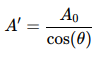
where θ = cos−1(v ⋅ n). As θ increases, the footprint expands and its shape transitions from circular to elliptical. The ratio of the ellipse’s major to minor axes can be expressed as
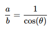
indicating that even moderate deviations from normal incidence substantially distort the sampled region.
Radiometric Consequences
Because the RGB sensor integrates reflected radiance across its entire footprint, any change in the shape or orientation of that footprint alters the distribution of sampled intensities. A pixel striking a surface at a shallow angle collects photons over a larger and more diverse area, including neighboring materials, shadows, and specular highlights. This effect produces systematic color variation with respect to viewing angle, even when the surface reflectance is isotropic. The problem is further compounded when the surface contains substructure or varying depth within the projected cone, as occurs in textured or irregular materials.
The resulting pixel color Ci can be expressed as the radiance-weighted average over the projected footprint Ωi :
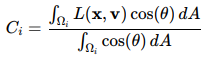
where L(x, v) is the reflected radiance at surface position x in viewing direction v. The cos(θ) term represents Lambertian foreshortening and ensures that regions viewed obliquely contribute less per unit area. However, because Ωi itself varies with θ, the integral aggregates different material regions at different view angles.
Implications for Multiview Normalization
In multi-scan datasets, the same surface patch is observed under varying θ for each scan position. Without explicit correction for these angle-dependent projection effects, attempts at white balance or color normalization across scans will be inconsistent. The RGB measurements will vary not only due to illumination and sensor response but also due to geometric projection differences. The radiometric calibration error increases proportionally with tan (θ), since both the footprint size and the contributing radiance distribution expand with angle.
This dependence introduces a directional bias in colorimetry that cannot be corrected through global normalization or gain balancing. Accurate cross-scan color calibration therefore requires estimating or recording the surface normal for each measured point, followed by normalization of the sampled radiance according to the incidence angle.
Integration with the VASL Framework
Within the Vossel-Aligned Spatial Lattice (VASL), the geometry of each measurement, including surface normal and viewing vector, can be recorded as part of the per-Vossel metadata. Each RGB observation stored in a Vossel is therefore accompanied by its angle of incidence θ and its projected footprint orientation. Radiometric fusion across multiple viewpoints can then be expressed as

where wk (p) represents the confidence weighting for observation k within the Vossel at location p. This formulation discounts samples taken at shallow incidence and promotes those captured closer to the surface normal, producing consistent radiometric normalization across all scan positions.
The inclusion of view-dependent geometry within the VASL structure provides the missing radiometric linkage between optical and active sensing domains. It ensures that color values are normalized not only by range and divergence but also by angular incidence, yielding stable and physically meaningful cross-scan colorimetric alignment.
Recap
The VASL method above represents a synthesis of prior corrective techniques, but here unified under a volumetric, proximity-based framework. Physical reprojection establishes the geometric foundation, range-dependent compensation provides radiometric normalization, and learned alignment fields refine residual errors. Within this structure, photometric attribution is determined by nearest-view proximity rather than fixed calibration. This selection of photometric centers, guided by spatial distance rather than image-space correspondence, distinguishes VASL from previous multimodal fusion approaches. It provides a physically accurate, data-complete representation suitable for coherent alignment and machine learning across optical, LiDAR, and radar domains.
Challenges in Visibility Masks
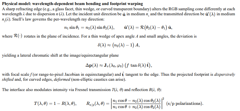
Chromatic PSF and “rainbow” Fringing
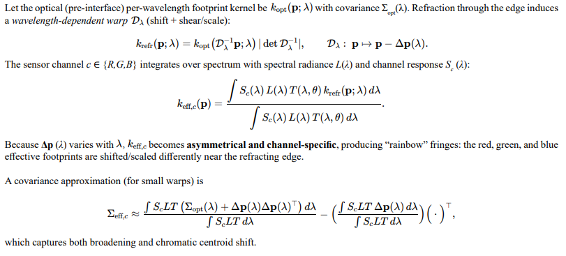
Diffraction/Refraction Coupling at Hard Edges
Sharp edges also introduce diffraction; the net field is a refracted/transmitted component plus a diffracted edge component, both wavelength dependent. In a scalar approximation, the knife-edge contribution along a path with Fresnel parameter ν(λ) adds an oscillatory tail:

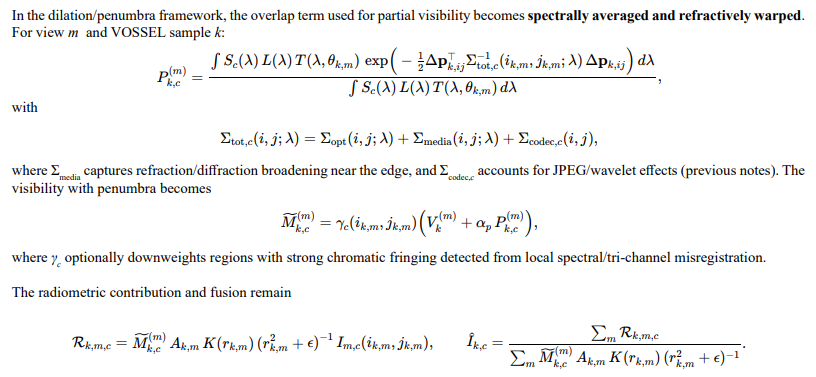
Integration into Dilation/Penumbra-Aware Visibility and Masking
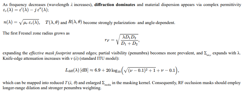
Frequency Scaling toward RF
Practical Implications for VOSSEL Masking
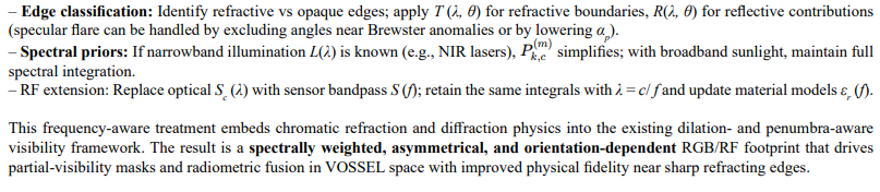
- Channel misregistration: Use per-channel geometric offsets Δpc estimated from edge neighborhoods to correct centroid shifts before overlap evaluation; residuals feed γc.
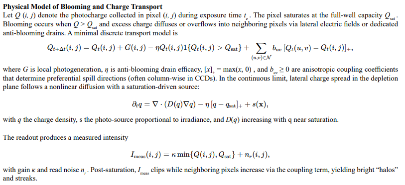
Sensor Blooming Impact on Visibility Masks
Blooming-Induced, Intensity-Dependent PSF
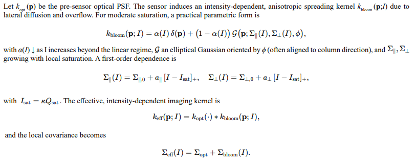
This yields asymmetric halos that expand with brightness and exposure.
Readout Smear and Rolling Effects

Channel Dependence and Spectral Coupling
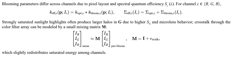
Incorporation into Visibility and Penumbra Weighting
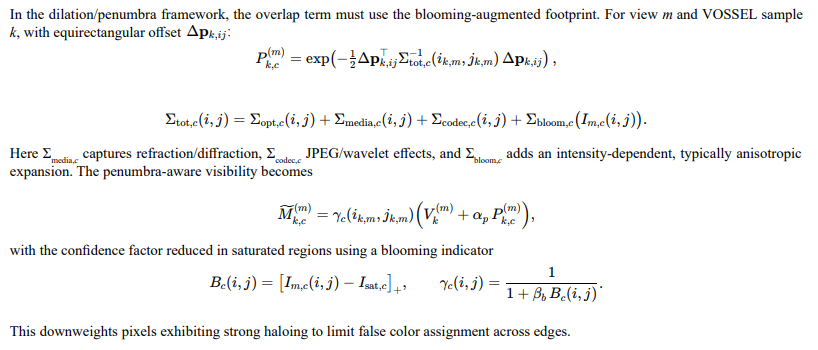
Interaction with Range-Dependent Compensation
Range compensation K (r) equalizes optical divergence but does not remove sensor-internal diffusion. The composite weighting entering radiometric fusion becomes

Estimation and Mitigation
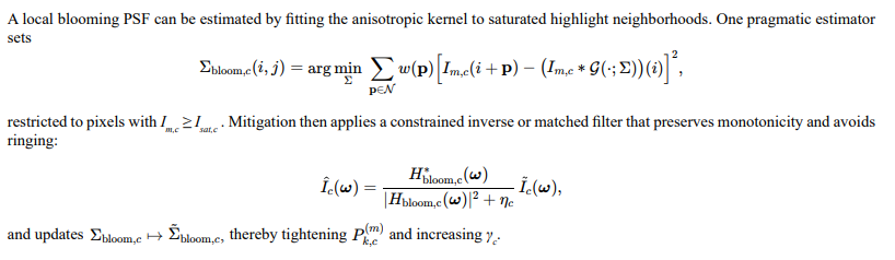
Practical Consequences for VOSSEL Masking
Blooming expands and skews the effective RGB footprint in a brightness-dependent manner, increasing apparent penumbra width and causing leakage of radiometry across geometric boundaries. Incorporating Σbloom,c (I) and a saturation-aware confidence γc into the visibility and overlap terms reduces erroneous assignments to occluded or adjacent structures. The effect is strongest for intense highlights and long exposures, aligns with sensor architecture (column or microlens layout), and persists independently of range-divergence corrections. This treatment maintains physical consistency inside the VOSSEL framework by separating optical divergence, media-induced warping, codec artifacts, and sensor-internal diffusion into additive covariance terms within the masking and fusion equations.
Lens Dirt and Fog Detection
Observation Model

Gain-Normalized Residuals

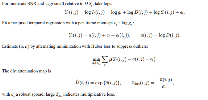
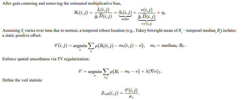
Over a long sequence with varying St, pixels affected by D <1 exhibit a persistent negative multiplicative bias; pixels affected by v >0 exhibit a persistent positive additive bias after centering.
Log-linear Decomposition for Multiplicative Dirt
Additive Veil Estimation for Fog/Flare
Scene-Motion Conditioning

Unified Contamination Confidence

Impact on PSF and Overlap Kernel
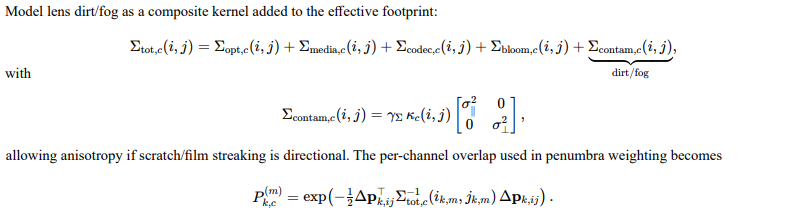
Contamination-Aware Visibility and Masking
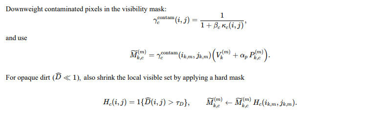
Low-rank+sparse Formulation (alternative)
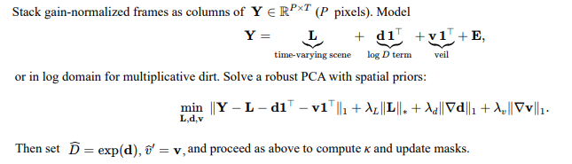
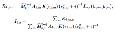
Integration into VOSSEL Fusion
Use the contamination-aware mask and PSF in radiometric fusion per channel:
Practical Notes

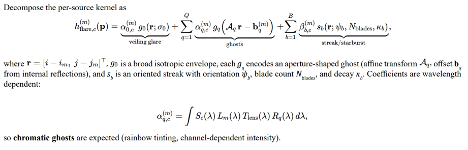
Lens Flare and Invalidation Masking
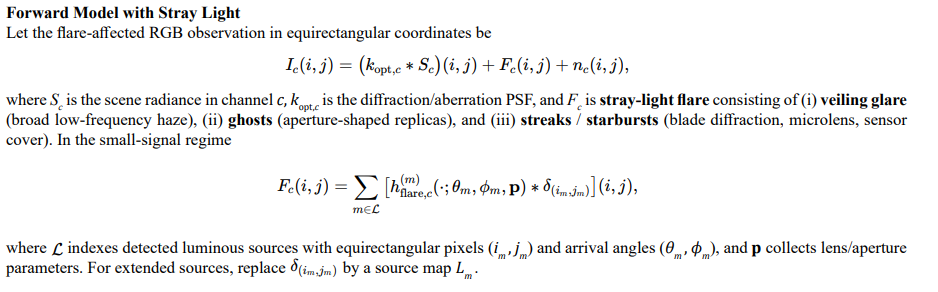
Parametric Flare Kernel
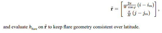
Equirectangular Metric Correction

Flare Source Detection

Blind/Semi-Blind Flare Field Estimation

Flare Invalidation and Soft Confidence
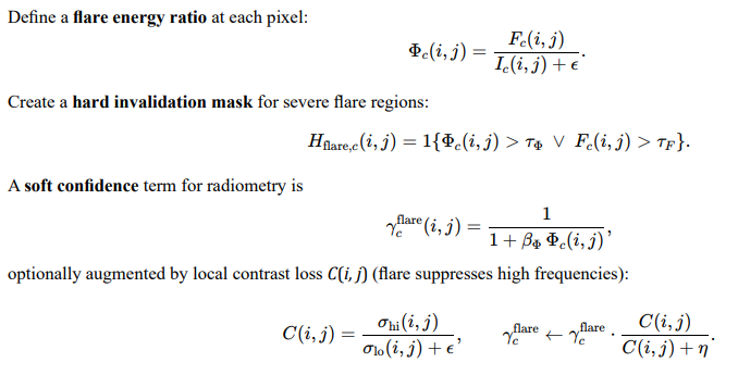
Impact on Overlap Kernel and Visibility Masking

Pixels flagged by Hflare contribute no radiometry to any VOSSEL. In soft regions (large Φ but below threshold), γcflare downweights contributions to curb color leakage.
Temporal and Multi-View Cues

Practical Detection Heuristics in Equirectangular Frames

Integration into Vossel Radiometric Fusion
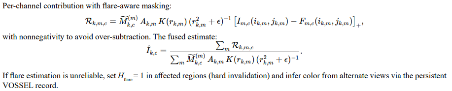
When to Prefer Invalidation Over Correction

JPEG Effects on Point-Spread and Occlusion Masking
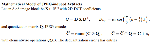
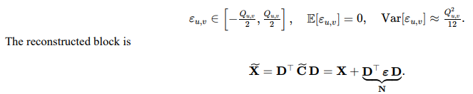
Blocking (block-edge discontinuities)

Ringing (Gibbs-like oscillations near edges)

Chroma subsampling (color bleeding)

Codec-Induced Point-Spread
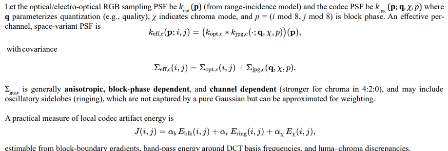
Artifact Suppression and Reconstruction
Common de-artifact operators can be expressed as proximal or filtering steps applied to the JPEG reconstruction X~
Deblocking (boundary-consistent smoothing)

Deringing (oscillation suppression near edges)

Chroma Upsampling Refinement

Asymmetric PSF and Impact on Visibility Masking
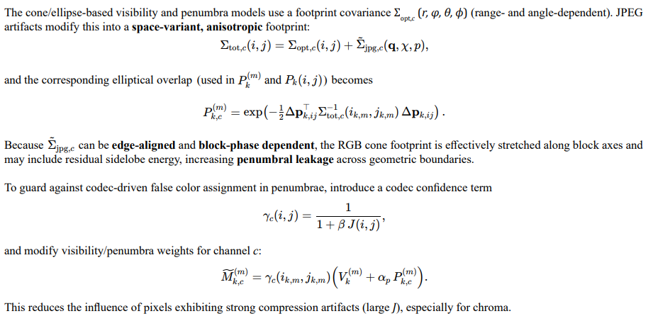
Integration into VOSSEL Radiometric Fusion
Per-channel radiometric contributions (with dilation- and penumbra-aware masking, Section above) become
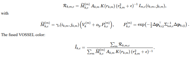
Practical Notes

Wavelet Compression Effects on Point-Spread and Occlusion Masking
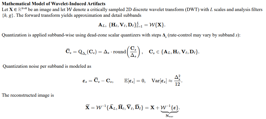
Pseudo-Gibbs and Shift-Variance Artifacts
where kanal captures net analysis/synthesis smoothing and ψs are wavelets at subband s. Oscillations are oriented (horizontal for H, vertical for V, diagonal for D ) and scale with Δs.
Tiling/Precinct Boundaries

Chroma Pathways
If the pipeline employs chroma subsampling or different quantization for chroma subbands, additional low-pass/phase errors arise analogous to luma–chroma asymmetry; denote these by Δχ sand model their effect in kwav,c below
Codec-Induced Point-Sprea
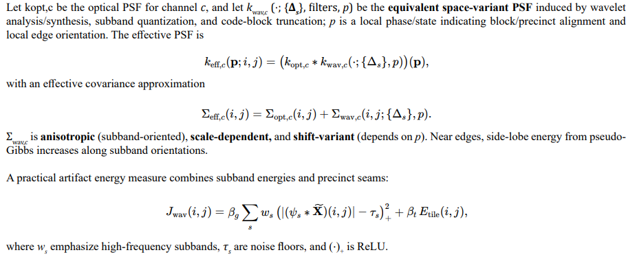
Artifact Suppression and Reconstruction

Edge-adaptive subband regularization

Precinct Seam Attenuation

Asymmetric PSF and Impact on Visibility Masking
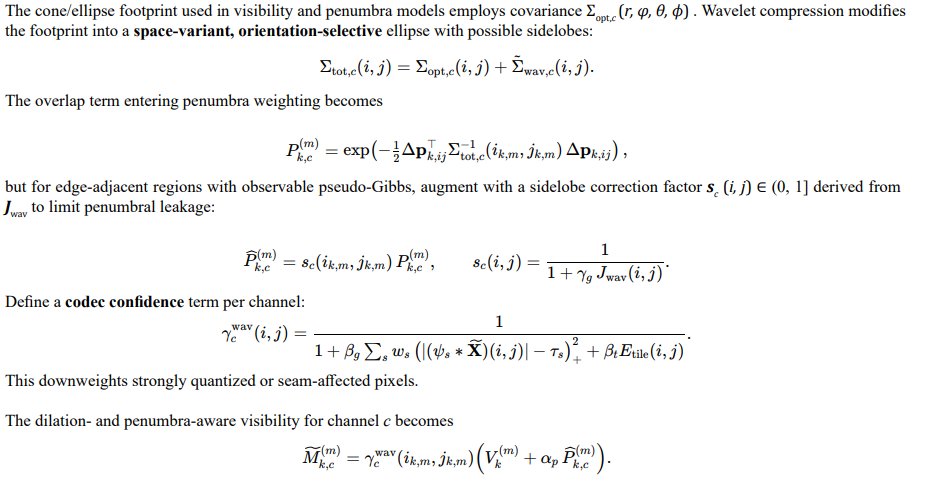
Integration of Wavelet-Aware Masking into VOSSEL Radiometric Fusion
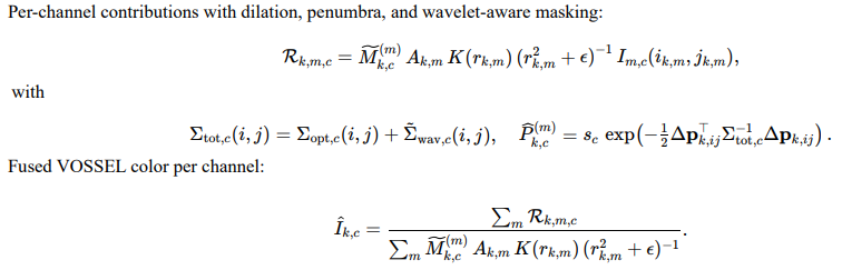
Practical Notes
– Subband step sizes {Δs} are often available from codestream headers; otherwise estimate via local variance of reconstructed subbands. Prefer undecimated/translation-invariant post-filters (cycle-spinning) to mitigate shift-variance pseudo-Gibbs before visibility- weighted fusion; update γcwav post-correction.
– Near high-contrast edges aligned with wavelet orientations, reduce αp or tighten sc to curb penumbral leakage driven by oscillatorysidelobes.
– If tiling is present, use overlap or seam-regularization to minimize Etile before computing Σtot,c .
This treatment embeds wavelet compression physics
—quantized subbands, shift-variance, precinct seams—into the existing range-, angle-, dilation-, and penumbra-aware visibility framework. The resulting space-variant, orientation-selective PSF informs both overlap and confidence terms in VOSSEL radiometric fusion, reducing false color assignment in penumbral and edge-adjacent regions.
Integration and Validation
An effective correction pipeline combines the above methods. Physical reprojection establishes the baseline geometry. Range-dependent convolution corrects divergence effects. Learned alignment fields refine residual nonlinear distortions. Occlusion masking excludes incompatible data. Validation proceeds by measuring alignment residuals at multiple ranges and incidence angles. Successful correction yields consistent feature alignment across modalities while maintaining scene geometry and structural continuity.
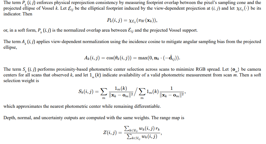
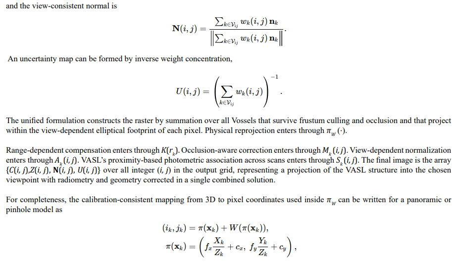
VASL Rendering Equation
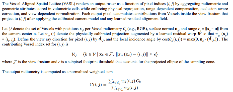
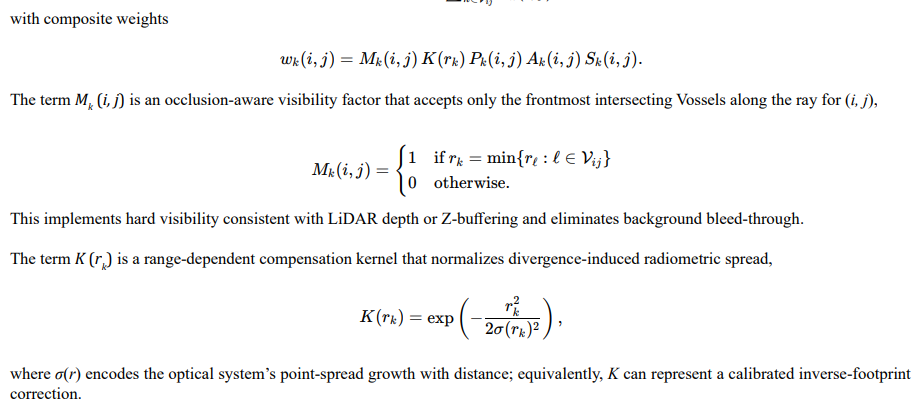

Implementation
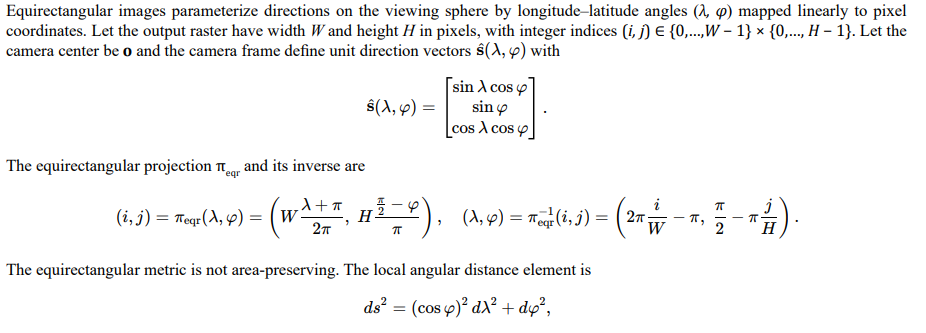
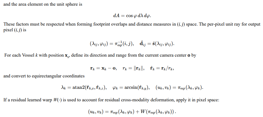
This section provides a software-ready formulation for rendering an output raster from a Vossel-Aligned Spatial Lattice (VASL) when both LiDAR-derived radiometry and RGB radiometry are stored as 360-degree equirectangular panoramas. The equations integrate physical reprojection, range-dependent compensation, occlusion-aware correction, and view-dependent RGB cone projection. The output raster is also produced in equirectangular format. All terms are explicitly defined for direct implementation.
Equirectangular Geometry and Projection
Inputs as Equirectangular Panoramas
LiDAR intensity or reflectance panoramas and RGB panoramas are stored per scan m in equirectangular form. For Vossel k observed by scan m, the per-scan photometric sample Ck,m is obtained by sampling the scan’s equirectangular image at (uk,m , vk,m) computed from om and xk through the same πeqr mapping. This maintains a consistent projection space for inputs and output.

View-Dependent Elliptical Footprint in Equirectangular Space
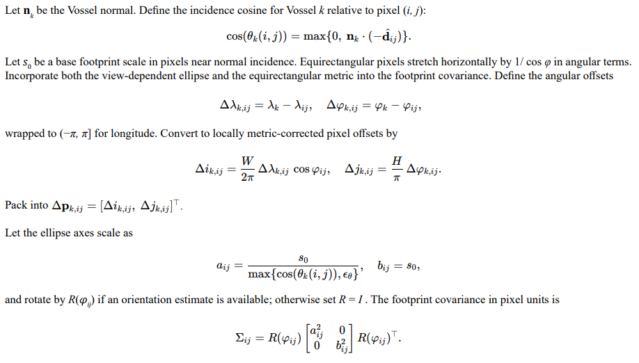
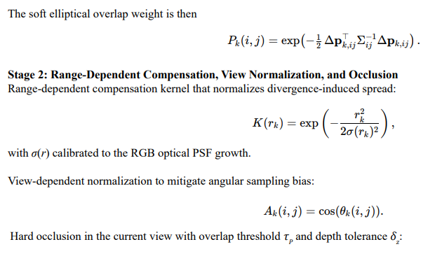

Equation in Equirectangular Output
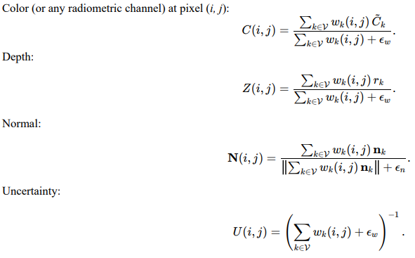
Summation With Per-Scan Proximity Fusion

Notes

Re-Rasterization of RGBZ into the Vossel Array
The corrected equirectangular output provides per-pixel radiometry and geometry as (C(i, j), Z(i, j), N(i, j), U(i, j)) in RGBZ form. The objective is to back-project this deep image into the Vossel lattice to augment, not replace, the original sensor measurements. All back-projected entries are marked as derived, maintain full provenance, and preserve the weighting parameters used at the time of derivation to enable later reweighting without loss of the raw measurements.
Inverse Mapping from RGBZ to Vossel Coordinates
For each output pixel (i, j), compute spherical direction and unit ray using the equirectangular inverse

Equirectangular Inverse and 3D Reconstruction
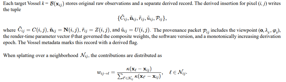
Accumulation and Fusion in the Vossel
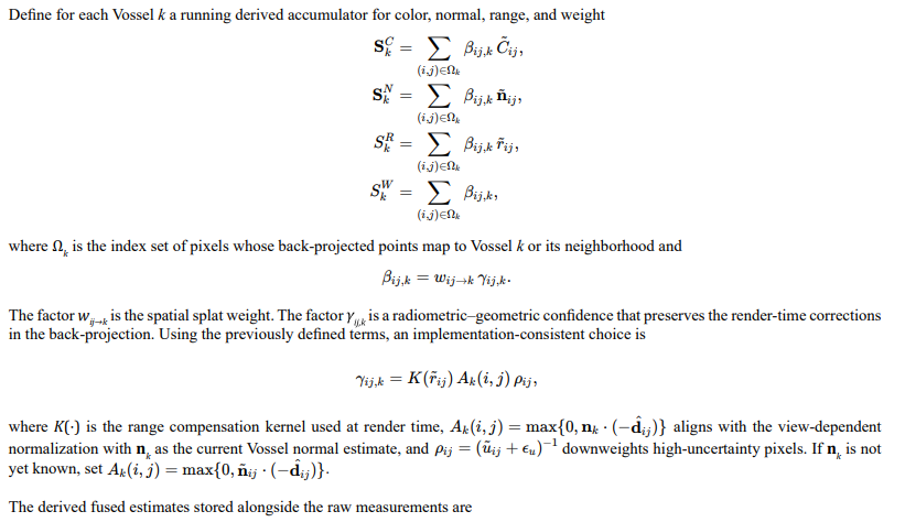

Preservation of Original Data and Reweighting

Sigma Form for the End-to-End Back-Projection
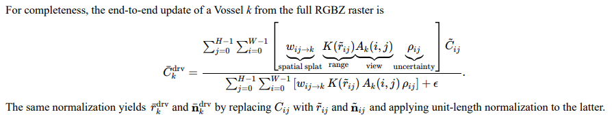
Handling Multi-Layer Depth
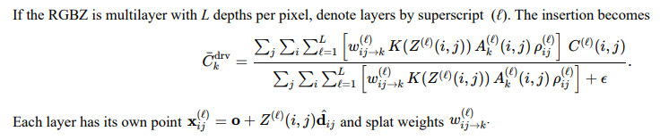
Data Flags and Versioning

Consistency with Equirectangular Space

Summary
Even after georectification, misalignment across optical, infrared, LiDAR, and radar systems arises from differences in divergence, aperture, and sampling behavior. Active sensors measure narrow, discrete returns, while passive sensors integrate over broader cones of radiance. The result is a physically consistent but geometrically incompatible set of measurements. Correction requires a hybrid approach combining reprojection, convolutional compensation, learned nonlinear alignment, and occlusion modeling. The unifying concept is the recognition of range-dependent beam divergence disparity, a physical property of multimodal sensing that must be modeled to achieve coherent fusion and accurate machine learning training.
References
- Wang, S., Rong, Z., Zhang, P., & Wu, Y. (2022). Accurate Extrinsic Calibration of LiDAR and Camera with Refined Vertex Features. In IPIN-WiP.
- Tang, W., Wang, B., Huang, L., Yang, X., Zhang, Q., Zhu, S., & Ma, Y. (2025). Calibration between a panoramic LiDAR and a limited field-of-view depth camera. Complex & Intelligent Systems, 11(1), 102.
- HogoNext. (2024). How to Address Beam Divergence Challenges in LiDAR Systems. HogoNext Technology Guide. https:// hogonext.com/how-to-address-beam-divergence-challenges-in-lidar-systems
- Chen, X., Sun, Q., & Hu, J. (2018). Generation of complete SAR geometric distortion maps based on DEM and neighbor gradient algorithm. Applied Sciences, 8(11), 2206.
- Wu, Y. Y., & Madson, A. (2024). Error sources of interferometric synthetic aperture radar satellites. Remote Sensing, 16(2), 354.
- Natural Resources Canada. (2025). Radar Image Distortions. Government of Canada. https://naturalresources.canada.ca/maps-tools-publications/satellite-elevation-air-photos/radar-image-distortions
- Tilley, D. G., & Yemc, D. J. (1994). Wave domain processing of synthetic aperture radar signals. Johns Hopkins APL Technical Digest, 15(3), 224-236.
- Cruz, H., Véstias, M., Monteiro, J., Neto, H., & Duarte, R. P. (2022). A review of synthetic-aperture radar image formation algorithms and implementations: A computational perspective. Remote Sensing, 14(5), 1258.
- Zhou, R., Sun, J., Hu, Y., & Qi, Y. (2018). Multichannel high resolution wide swath SAR imaging for hypersonic air vehicle with curved trajectory. Sensors, 18(2), 411.
- Passmore, G. (2025, October). A Unified ISR World Model: Vossels, Voxels, Mipvols, and Reinforcement Learning. DOI: 10.13140/ RG.2.2.15734.05443