
Journal of Applied Material Science & Engineering Research(AMSE)
ISSN: 2689-1204 | DOI: 10.33140/AMSE
Impact Factor: 0.98

Research Article - (2023) Volume 7, Issue 2
Characterization of the Microstructure of A Breakout Steel Sample
2Quality Manager, Gerdau Long Steel North America, Jackson Mill, TN 38305, USA
3Improvement Facilitator, Gerdau Long Steel North America, Jackson Mill, TN 38305, USA
Received Date: Sep 30, 2023 / Accepted Date: Oct 17, 2023 / Published Date: Nov 13, 2023
Copyright: ©Ã?©2023 Ignatius C. Okafor, et al. This is an open-access article distributed under the terms of the Creative Commons Attribution License, which permits unrestricted use, distribution, and reproduction in any medium, provided the original author and source are credited.
Citation: Okafor, I. C., Lovell, B., Ambrosio, D. (2023). Characterization of the Microstructure of a Breakout Steel Sample. J App Mat Sci & Engg Res, 7(2), 150-165.
Abstract
The microstructure of a continuously cast break out of low carbon steel has been studied using optical microscopy; SEM/EDS and EBSD analysis techniques. SEM and EBSD studies were carried out on two different locations on one sample piece and the resulting room temperature grains were found to be mostly BCC α- ferrite phase. Their orientations (using Euler angles) were determined. No meaningful amount of FCC phase was indexed after two patterns indexed on the two locations of the sample piece. The FCC comprised only 0.02% to 0.08% of the total patterns indexed. EBSD maps for the two locations, along with pole figures and grain size charts were deduced for the BCC phase. Volume fraction of the phase was estimated. Reconstruction of the Prior Austenite Grain Boundary was made from the alpha grains data using AztecWave software (AZtecCrystal). Only a small amount of the prior austenite grain boundaries was determined suggesting that the size of the parent grains were significantly larger than the map area in each case.
Introduction
Steel strand rupturing is a common issue in continuous casting of both billets and slabs. Unlike in the slab casting industry where various technologies have been developed to predict possible breakouts, the billet industry counterpart is handicapped by the mold geometry that is the size and number of molds needed in each caster (4 to 8 and counting). The technology therein is not as robust most likely due to cost.
When this breakout occurred therefore, we thought we could learn a few things from both the cause of the event and the metallurgy associated with the said steel chemistry. The theory and processes associated with steel breakouts have been well documented in literature. Savage and Pritchard postulated that the steel strand shell tears near the meniscus when the upper part of the shell adheres to the mold [1]. Another author suggested that when mold powder is used as a lubricant, it forms a high carbon area in the solidifying shell which is weak and inhibits proper flux flow and that initiates a tear in the shell [2]. The use of oil lubrication offers a different challenge mostly coming from inadequate oil flow. The lack of enough oil distribution and uneven lubrication of the solidifying steel shell causes sticking to the mold. In general, it is known that the following parameters do influence breakouts in billet steel manufacturing.
- Relative humidity and Hydrogen presence in the atmosphere
- Liquid steel temperature
- Mold level fluctuation
- Mold oscillation
- Steel composition- peritectic or otherwise
- Casting speed and so steel residence time in the mold
- Uneven strand cooling.
This work took a quick look at what may have caused the breakout and proposed preventive actions going forward. This is in an internal report.
The work also aims to characterize the room temperature grain structure from the solidified shell and also attempted a reconstruction of the prior austenite grain size.
Phase transformation from the austenite phase (ϒ) to ferrite phase (α) is responsible for control of microstructures of steel products and the mechanical properties. Prior austenite microstructure (before transformation) influences the said mechanical properties. Therefore, information about the prior austenite microstructure has become of much interest.
Consequently, methods to acquire information about prior austenite microstructmicrostructure using data of crystal orientations. The principle is based on Euler angles’ crystal orientation relationships. Information exists in the literature for the use of these methods on martensite and bainitic starting microstructures, but not much on low carbon low alloy steels. The paucity of information in the literature for this class of steel served as a major motivation for this aspect of the work. Maps derived from EBSD techniques offer the possibility of directly inferring the parent (ϒ) microstructure from the inherited one [10-12]. In this work we have used EBSD data to reconstruct the prior austenite grain size using the AztecWave Software in low carbon low alloy steel.ures have been assiduously researched and developed [3-7]. Many commercially available computer programs (including MTEX8 and Aztec9 Wave; Aztec Crystal) now exist that enable reconstruction of prior austenite.
Metallography
Material
Samples from low carbon low alloy steel used in this study were obtained from a functioning steel mill. The said steel is from a breakout heat. The breakout was reported to be because of shell sticking to the mold during continuous casting. The samples were therefore completely air cooled in uncontrolled ambient atmosphere.
Microstructure
Microstructural studies were carried out in longitudinal and transverse directions. Samples were cut using the Buehler abrasive cut off machine. They were then mounted in Bakelite using the water- cooled LECO MX 500.
Mounted samples were polished using the STRUERS Tegramin 25 polisher. They were ground through Piano’s 200, and 1200 metallic grits and polished thereafter through various steps to the following micron sizes: 9 μm; 3 μm; 1 μm and ¼ μm using Diamond Suspension in that order. Samples were washed out with water and etched in 2% - 3% Nital. Etched samples were studied under a Zeiss Microscope at magnification 200x.
SEM – EBSD STUDY
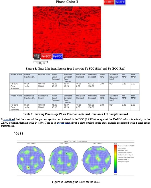
SEM and EBSD data were obtained at the The McCrone Group laboratory. For the scanning electron microscopy (SEM) imaging, EBSD and X-ray spectroscopy (EDS) analyses, samples were prepared using standard grinding and polishing procedures. The mechanically polished surface was etched in Nital-2% concentrated HNO3 in ethanol for a few seconds for SEM. Each sample was further polished using the Leica TIC3X triple ion beam polisher. Even though the polish was considered good it still had about 15% zero solutions. That is areas producing no patterns or unindexable patterns, which were likely due to variations in the surface finish. The SEM equipment was set at Accelerating Voltage of 20.22Kv; Specimen Tilt (degree) of 70.00; Hit Rate of 78.88% and Speed of Acquisition set at 40.32Hz.
Results
Optical Microscopy
The microstructure of the sample showed various patterns that ranged from typical dendritic morphology (see Fig. 1 A, F and G) through as-cast solidified ferrite structure. However, the primary microstructure is acicular ferrite (Fig. C, D, and E) and granular bainite with some allotriomorphic ferrite (Fig. 1 C, D, and E). Some of microstructures are shown below.
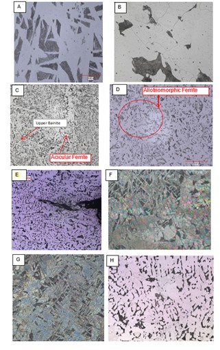
Figure 1: (A – H) The micrographs A through H show various areas from the low carbon steel that cooled in air upon break out during continuous casting. (B) shows more ferrite and a film of cementite (white) around the pearlite. The rest of the micrographs (C through H) show typical as-cast microstructures at various stages of solidification; the dendrites of the columnar zone (F and G), acicular ferrites (C), polygonal ferrites and alotromorphic ferrite (H).
SEM – EBSD
A sample supplied to the third-party laboratory was already polished to 1 micro surface finish. But since EBSD (Electron Backscatter Patterns) originate from depths on the order of tens of nanometers of a sample the said sample needed more polishing. The sample contained a large void extending through its thickness with smaller voids on the polished surface. In order to avoid polishing media from filling the voids, they were filled with EpoThinTM epoxy using a syringe. The epoxy was allowed to cure overnight.
Sample was then polished using 1200 grit SiC paper followed by 3 μm, 1 μm, and 0.25 μm diamond paste. A triple ion beam (argon) polisher was used as the final polishing step. EBSD mapping was performed before the he SEM/EDS analysis to avoid the possibility of carbon being deposited on the newly polished surface during SEM/EDS analysis. The maps were obtained at 250X (field of view approximately 0.51 mm x 0.39 mm) from two different areas a few weeks apart.
Theory of Parent Grain Reconstruction
Phase transformation occurs through the operation of an orientation relationship (OR). According to Bhadeshia an OR refers to the coherent geometric parallelism between specific planes and directions of parent–child crystal symmetries on either side of their common boundary segment. In all parent– child crystal symmetry combinations, one or more favored ORs exist that provide the best fit at their boundary segment interfaces and enable crystallographic phase transformation between them [13].
Orientation relationships (OR) occur in both displacive (Diffusionless - like martensitic) transformations and diffusion (growth-based transformation occurring at high temperatures). Diffusion based transformations often involve chemical atomic transfers and so chemical composition differences which could result in the loss of atomic correspondence between parent and daughter.
For either case the theory behind their (OR) computation has evolved from solving rigorous manual mathematical Rotation Matrices as detailed in Bhadeshia to the use of digital computational analysis. In their work, Cheng-Yao Huang et. al. devised a 3-step process (see Fig. 2) for parent grain reconstruction involving (i) the refinement of the orientation relationship, (ii) Orientation Coalescence and (iii) a voting process [13-16]. These steps are really better described by the authors than we could. They depicted the said processes graphically as hereunder:
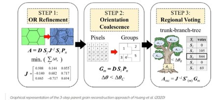
Figure 2: Orientation maps showing the benefit of orientation refinement for the successful parent grain reconstruction in martensite.
The major motivation in this portion of the study derives from interest in the crystallographic information that could be obtained and used for understanding prior austenite grain boundary in low carbon steels. Even though most of the reconstruction calculations have been based on Austenite (FCC) to Martensite (TCP) structures and vice versa, this work utilizes only acicular ferrite and bainitic microstructures that resulted from the transformed low carbon in this alloy (0.14Wt.%C max).
Diffusionless transformation from austenite (ϒ) to martensite (á¼ÂÃÃÂ??ÂÃÂ?ÂÂ) occurs according to a fixed crystallographic orientation relationship (OR). Up to 24 orientational variants may satisfy the OR in this situation. X- ray diffraction had been used to identify ORs in mild steel, by Kurdjumov-Sachs (KS) [15-18].
This transformation from austenite (parent) to martensite (daughter) is usually achieved by quenching or rapid cooling from a high temperature[17,18]. In martensitic transformation, there are 24 equivalent variants of martensite capable of forming one prior austenite grain based on transformation crystallography, or orientation relationship (OR). Ideally these 24 variants would occupy the prior austenite grain in the same volume fraction [14, 15].
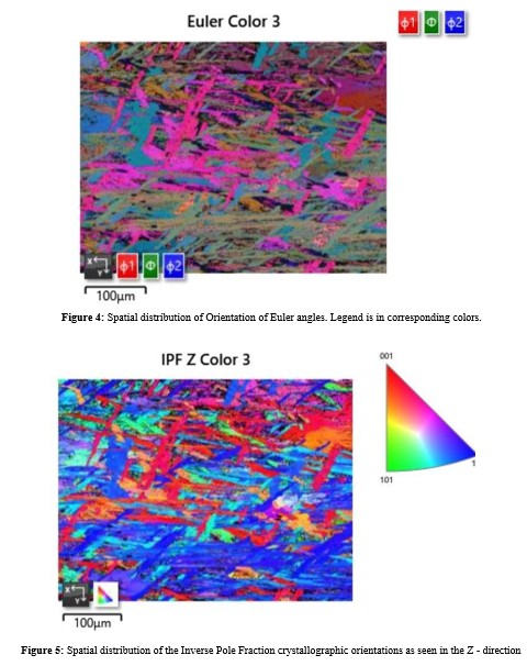
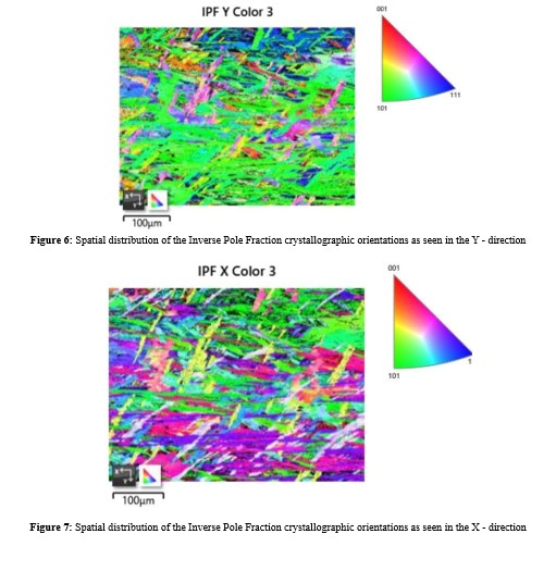
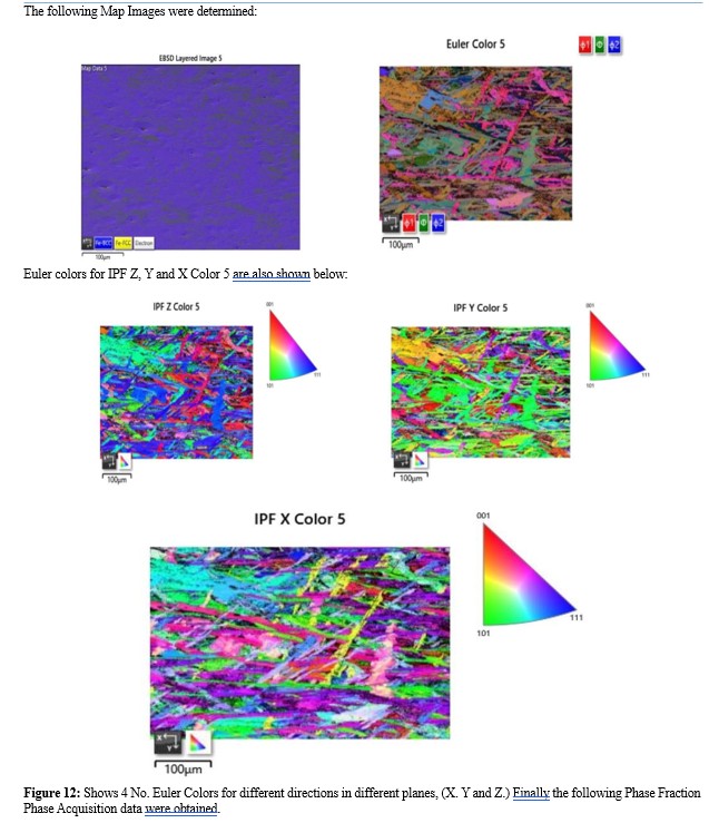
Patterns were studied from two (indexed) spots of one sample using the electron beam backscatter. Since EBSPs originate from depths on the order of the top tens of nanometers of the sample, samples were polished several times for EBSD mapping as already described above. Electron backscatter diffraction orientation data from commercial software are typically in the form of a set of Euler angles for each X, Y, and Z positions on the sample surface. Such EBSD data were therefore collected in this study.
The map acquisitions were set up to index both the BCC and the FCC phases of steel. No meaningful number of FCC patterns were indexed for either map (patterns indexing as FCC comprised approximately 0.02% to 0.08% of the total patterns indexed), therefore, the data were reprocessed using only the BCC phase. Typical data from both the BCC and FCC and the BCC only maps are presented below for Map Area 1 and Map Area 2.
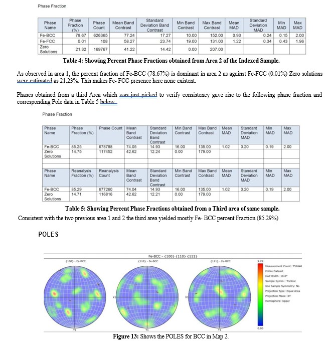
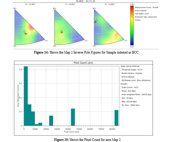
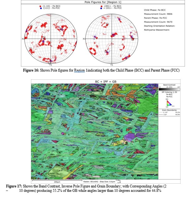
EBSD Map Area 1: Maps, Pole Figures, and Grain Size Charts are presented.
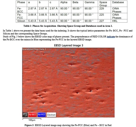
Figures 4 through 6 below show color spatial distribution of Euler angles in both Pole fractions or Inverted Pole Fractions as indicated below each figure. For each figure there is an accompaning color legend for ease of understanding.
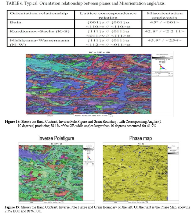
Parent Phase Reconstruction
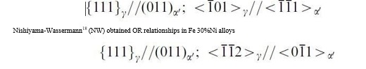
An attempt was made to reconstruct the parent phase from the BCC data obtained in this study using the Aztec Crystal software. The austenite grain has a specific orientation relationship with the ferrite matrix derived from it. Grains that have been formed by a α - γ or vice-versa phase transformation should show a Bain, Nishiyama - Wassermann (N-W), or Kurdjumov-Sachs (K-S) orientation relationship. These orientation relationships can be described as a rotation of an angle ä about a common crystallographic axis (axis of rotation). This angle and axis are known as the angle/axis pair. Table 1 shows typical Orientation relationships between austenite (γ) and ferrite (α) matrix.
In this work, a Nishiyama – Wassermann relationship was used.
Typically, one can see the outline of the parent grains which allows one to “train” the software to interpret the child/parent relationship(s). But there were no apparent parent outlines, suggesting that the size of the parent grains were significantly larger than the map area. It is perhaps pertinent to point out that the sample was from a breakout heat at high casting temperatures. These high temperatures create large austenitic grain sizes as opposed to a rolled sample piece, which could have smaller austenitic parent grains. In theory, one should still be able to process the data, but it did not seem to create the expected singular parent orientation. Much of the results obtained with our data is shown below. The blue segmentation represents the FCC Parent Phase.
Discussion
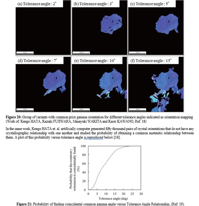
Kengo HATA et. al. reported in their work, using the theoretical approach, where tolerance angles were set at various angles within the range of 2–15 degrees [18]. They continued the analysis when the misorientation θ was within the tolerance angle. The result is shown in Fig. 20 below.
In their work Kengo HATA reported that when the tolerance angle was set at 2 degrees (Fig. 20(a) below), the analysis failed to discover any common austenite orientation with adjacent variants. Therefore, no grain is shown in the figure. This is because the tolerance angle is set too low to discover a common austenite orientation. When the tolerance angles are 3 degrees or above, martensite variants having a common austenite orientation were discovered. They further reported that its region expanded greatly as the tolerance angle is increased. These results clearly indicate that the analysis of common austenite grains can vary depending on the tolerance angle. The group of plots shown below (Fig. 20) are taken from the work of Kengo HATA et al. for clarity.
Conclusion
- Optical Microscopy studies were performed on several samples from a breakout low carbon steel heat.
- The microstructure was as expected mostly acicular ferrite, polygonal ferrite and alotromorphic ferrite.
- SEM/EDS and EBSD analysis were used to determine the grain size, phase fractions and Orientation Relationships (OR) of the grains present.
- The sample was mostly comprised of alpha ferrite phase.
- Data from EBSD were used to determine Prior Austenite Grain Boundary and the result was not sufficient to generate a lot of grains because the initial scan area was small, and the pole figures suggest possible one or two grains there from.
Acknowledgements
The authors acknowledge the invaluable discussions / assistance received from Prof. Hung-Wei (Homer) Yen of The National University of Taiwan. His very experienced contributions in discussions are truly appreciated. The selfless contributions of Sam Pennington and Richard Mclaughlin of Oxford instruments are gratefully acknowledged. The authors are grateful to Gerdau Long Steel North America for allowing the use of its facilities for this work.
Conflict Of Interest
The authors declare no potential conflict of interest.
References
- Savage, J., & Pritchard, W. H. (1954). The problem of rupture of the billet in the continuous casting of steel. Journal of the Iron and Steel Institute, 178(3), 269-277.
- T. Mukai, K. Yamaguchi, and S. Ogibayashi: Tetsu - to - Hagane, 71 (1985), SI025; Trans. Iron Steel Inst. Jpn., 26 (1986), B163.
- Cayron, C., Artaud, B., & Briottet, L. (2006). Reconstruction of parent grains from EBSD data. Materials characterization, 57(4-5), 386-401.
- Miyamoto, G., Iwata, N., Takayama, N., & Furuhara, T. (2011). Reconstruction of parent austenite grain structure based on crystal orientation map of bainite with and without ausforming. ISIJ international, 51(7), 1174-1178.
- Morimoto, T., Yoshida, F., Chikushi, I., Kitahara, H., & Tsuji, N. (2007). Development of variant analysis program by using EBSD data. Tetsu-to-Hagane(Journal of the Iron and Steel Institute of Japan), 93(9), 591-599.
- Humbert, M., Moustahfid, H., Wagner, F., & Philippe, M. J. (1994). Evaluation of the high temperature texture of the [Beta] phase of a TA6V sample from the individual orientations of grains of the low temperature [alpha] phase. Scripta Metallurgica et Materialia;(United States), 30(3).
- Humbert, M., & Gey, N. (2002). The calculation of a parent grain orientation from inherited variants for approximate (bcc–hcp) orientation relations. Journal of applied crystallography, 35(4), 401-405.
- MTEX: https://mtex-toolbox.github.io/index
- AztecWave: https://plus-c.aztecsoftware.com/
- S. Bechet, L. Beaujard: Revue de Metallurgie Vol. 10 (1995), 830-6.
- G. Bruckner, A. Köntges and G. Gottstein. (2001). Characterization of the Microstructure of a Breakout Steel Sample. ISIJ International, 41(5), 468.
- Snape, E., & Church, N. L. (1972). Microduplex processing of low alloy steels. JOM, 24, 23-29.
- Kurdjumow, G., & Sachs, G. (1930). Über den mechanismus der stahlhärtung. Zeitschrift für Physik, 64(5-6), 325-343..
- Nambu, S., Shibuta, N., Ojima, M., Inoue, J., Koseki, T., & Bhadeshia, H. K. D. H. (2013). In situ observations and crystallographic analysis of martensitic transformation in steel. Acta materialia, 61(13), 4831-4839.
- Kitahara, H., Ueji, R., Tsuji, N., & Minamino, Y. (2006). Crystallographic features of lath martensite in low-carbon steel. Acta materialia, 54(5), 1279-1288.
- Nishiyama, Z. (1934). X-ray investigation of the mechanism of the transformation from face centered cubic lattice to body centered cubic. Sci. Rep. Tohoku Univ., 23, 637.
- Wassermann, G. (1935). Uber den Mechanismus der a À> c Umwandlung des Eisens (On the Mechanism of the a À> c Transformation of Iron). Mitteilungen aus dem Kaiser Wilhelm Institut fu r Eisenforschung, 17, 149-55.
- Hata, K., Fujiwara, K., Wakita, M., Kawano, K. (2017). Nippon steel & Sumitomo Metal Technical Report No. 114, 28.