
Japanese Journal of Medical Science(JJMS)
ISSN: 2996-2536 | DOI: 10.33140/JJMS


Research Article - (2026) Volume 4, Issue 1
CAD-CAM Full Digital Dentures: An Enhanced Workflow In Clinical And Laboratory Workflow
2specialist in orthodontics and implantology working in the private sector in Casablanca, Morocco
3Head of the removable prosthodontic department at the D.C.T.C of Casablanca, Director of the national diploma of removable prosthodontics, Morocco
Received Date: Aug 01, 2025 / Accepted Date: Dec 15, 2025 / Published Date: Jan 16, 2026
Copyright: ©2026 Nidal Elmoutawakkil, et al. This is an open-access article distributed under the terms of the Creative Commons Attribution License, which permits unrestricted use, distribution, and reproduction in any medium, provided the original author and source are credited.
Citation: Elmoutawakkil, N., Elmoutawakkil, D., Hacib, N., Bellemkhannate, S. (2026). CAD-CAM Full Digital Dentures: An Enhanced Workflow In Clinical And Laboratory Workflow. Japan J Med Sci, 4(1), 01-17.
Abstract
In the age of emerging technologies, the procedures within the removable prosthodontics department have experienced numerous transformations, leading to decreased laboratory time, fewer chairside sessions, and a reduction in the total expense associated with complete dentures. This study intends to illustrate, via a clinical case, the stages of computer- assisted design and manufacturing while highlighting the distinctions between the two processes utilized in creating two complete dentures at the dental consultation and treatment center (D. C. T. C) in Casablanca.
Keywords
CAD-CAM, Full Dentures, Functional Impressions
Introduction
The creation of complete dentures requires a complex and meticulous protocol. It requires not only technical skill but also significant rigor in monitoring procedures, particularly because aging complicates patient cooperation, especially during impression taking. The use of digital impressions promotes, in addition to treatment success, patient comfort by reducing the number of manipulations and eliminating additional casting steps. In this way, the implementation of a digital workflow significantly reduces inaccuracies and human errors during the fabrication of complete dentures. It also shortens the production line; this time saving is combined with a significant improvement in the accuracy of digital dentures. The objective of this article is to demonstrate, through a clinical case, the relevance of the different workflows used for computer-designed and manufactured complete dentures, to highlight the benefits, constraints, and technical specificities of the method employed.
Materials and Methods
Clinical Examination
Mr. M. O. , aged 68, visited the removable prosthesis department at the Casablanca Dental Consultation and Treatment Center (CCTD) for a consultation regarding the replacement of his worn and non-retentive complete denture for the mandible (Figure 1). An intraoral assessment showed that the mandibular arch was entirely edentulous, whereas the maxillary arch featured a complete bridge (Figure 2).
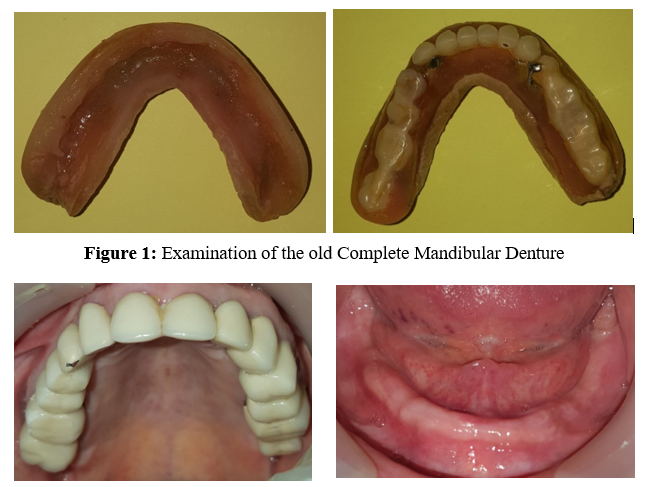
Figure 2: Intra-Oral Examination\
Theoc clusal assessment indicates a Class I occlusion and demonstrates thatthe existing prosthetic space is adequate in all three spatial dimensions (figure 3).
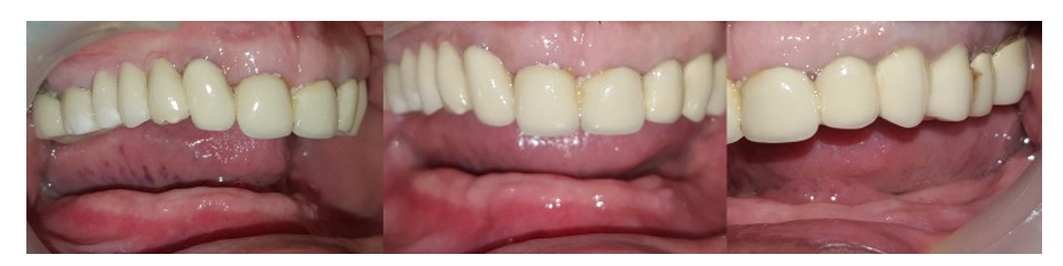
Figure 3: Occlusal Examination
Primary Impressions
In the mandible, we created a traditional primary plaster impression (Snow white®) utilizing a commercial impression tray (figure 4),which was then digitized with an intraoral scanner (Medit 500 i®). In the maxilla, we conducted an optical impression using the same intraoral scanner referenced earlier (figure 5).

Figure 4: Primary Mandibular Impression Using Plaster

Figure 5: Primary Optical Impression in the Maxilla
Primary Mandibular Impression’s Virtual Cast
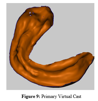
Upon importing the STL file of the primary mandibular impression into the open-source software (Meshmixer ®), we initially iden-tified the usable impression’s limites (figure 6). Next, we invert- ed its intrados to create a virtual cast (figure 7). Finally, after re¬fining the edges and removing the impression residues (figure 8), we successfully produced the final primary model (figure 9).

Figure 6: Determination of the Impression’s Exploitable Limites
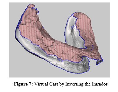

Figure 8: Edges Refining
Computer-Aided Design of the Individual Mandibular Impression Tray
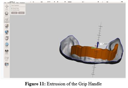
The external surface of the primary model was duplicated in order to create the individual impression tray which was spaced 1. 5mm from the primary model (figure 10), Following this, a 2mm rectangle was sketched on the outer surface of the individual impression tray, which was then extruded to a length of 15mm (figure 11). This contraption will first function as a grip handle while capturing the secondary impression, onto which a wax rim wax will be mounted to recordthe intermaxillary relationships.

Figure 10: Individual Tray Spaced 1.5mm from the Primary Cast
Computer-Aided Manufacturing of the Individual Mandibular Impression Tray
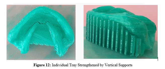
The deviced sketched using Meshmixer ® software was exported to an XYZ 1.0 junior 3D printer using the FDM (Fused Deposition Modeling) hot material deposition technique, from a PLA spool with a filament diameter of 1.75 mm (polylactic acid) extruded from a 4 mm nozzle; The use of vertical supports and a bed affixed to the extrados of the individual tray (Figure 12) not only strengthened the structure of the printed tray but also allowed the entire printed prosthetic device to remain intact.
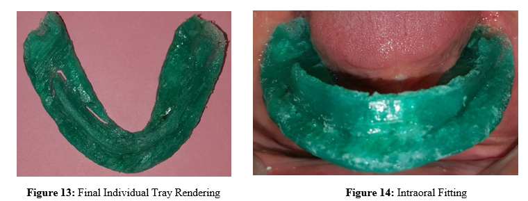
Upon the manual removal of the vertical supports and the supporting bed, the individual tray achieved a final flawless look, along with smooth,roundededges devoid of any rough patches, after a brief refinement of its outer surface using sandpaper (figure 13). The intraoral fitting adaptation and stability, with retention have been observed (figure 14).
Functional Secondary Mandibular Impression
Impression of functional margins was done (figure 15) using a thermoplastic paste (Kerr® paste), the adhesive coating (figure 16) was then carried out using a medium viscosity polysulfide (Permlastic Regular®).

Figure 15: Impression of Functional Margins using Kerr Paste®
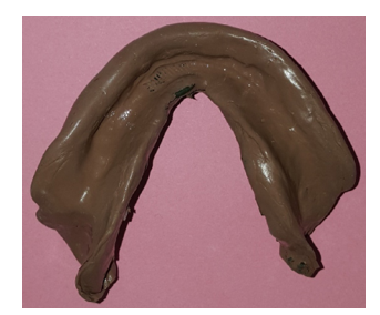
Figure 16: Adhesive Coating using Permlastic Regular®
Occlusal Rims
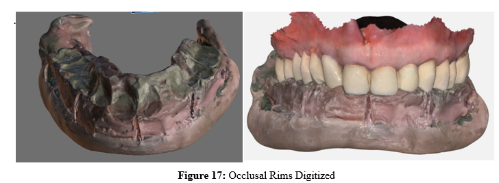
A pink wax rim was mounted in a saddle on the tray’s grip handle, respecting the patient's vertical occlusion dimension and the prosthetic corridor in harmony with good lip support and correct phonation, the intermaxillary relationships were recorded using Aluwax® occlusion wax. We digitized the secondary impression and the recorded occlusal rims, both intraorally and outside the oral cavity (Figure 17).
Virtual Cast of the Functional Secondary Mandibular Impression
We performed the virtual casting of the secondary impressions using Meshmixer® software in several stages. First, we removed the occlusal part, then, like the virtual casting of the primary impression, we inverted the intrados of the secondary impression. Extrusion of the edges of the latter allowed us to obtain the entablature and the base of the cast (Figure 18). Although it is of no interest in the computer-aided design and manufacturing protocol for complete dentures, the printing of the secondary model in PLA was carried out for educational purposes (Figure 19).
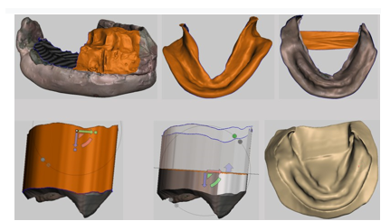
Figure 18: Virtual Cast of the Functional Secondary Mandibular Impression (Meshmixer)
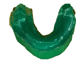
Figure 19: 3D Printed Cast Using PLA
Computer Aided Design of the Mandibular Denture (Blue Sky Bio® software)
Secondary Cast Import
In order to correctly position the secondary model when imported to the software, it requires several points to be specified:
• the arch concerned (maxillary or mandibular)
• the nature of the arch (toothed, totally or partially edentulous)
Then, three anatomical landmarks specific to each arch must be marked: in the maxilla, the location of the two pterygomaxillary ligaments and the retroincisive papilla must be marked, while in the mandible, the most posterior part of the trigones and the medial frenulum must be marked. The software then offers the possibility of correcting the three-dimensional orientation of the secondary model (Figure 20).
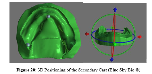
Import du Modèle Maxillaire
Just as we described previously, the import of the maxillary STL model involves the positioning of three reference points: the mesial edge of the incisal edge of the 11 and the two mesiopalatal cusps of the last molars (figure 21).

Figure 21: 3D Positioning of the Maxillary Cast (Blue Sky Bio®
Occlusal Orientation of the Casts
In the interest to ensure the correct spatial positioning of the two models, the STL files of the mandibular occlusion model digitized outside the mouth (in blue) were imported, and the two STL files of the same model digitized intraorally in centric relationship (red and green). These three STL files will be used throughout the design of the denture as reference points, in fact the virtual teeth must fit into the prosthetic corridor defined by these files (figure 22).

Figure 22: Occlusion of the Two Casts (Blue Sky Bio ®)
Teeth Mounting
After selecting the mandibular secondary model as the denture design support, clicking on the order button ; then a panel appears allowing you to select the teeth to be inserted. There are two options:
• Choose from the 10 virtual tooth libraries available in the software, with the ability to modify the dimensions of each tooth and export them for later printing.
• Choose from the 7 physical tooth libraries, without being able to modify the dimensions of the teeth or export them later. These teeth are marketed by the company "Nobildent." However, the software offers the option of designing a reduction guide to adapt the heel of the teeth to the alveolar denture base.
We opted for virtual teeth (BRENES SQUARD), firstly because the slightly disrupted occlusal plane requires adapting the posterior sectors to the proportions of the maxillary bridge, and secondly because the deadline for exporting the set of teeth was extended due to the global pandemic caused by the Covid-19 virus. This is how we first inserted the anteroinferior sector (figure 23) followed by the posterior sectors while ensuring the ovejet and the overbite (figure 24).
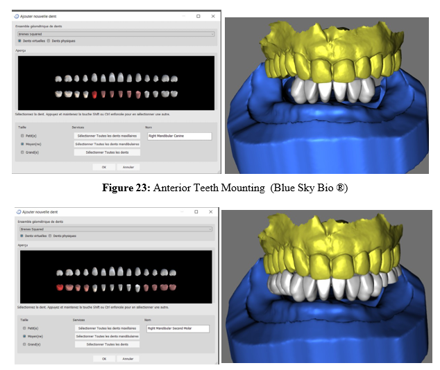
Figure 24: Posterior theeth Mounting (Blue Sky Bio ®)
Insertion Axis Definition
The insertion axis of the denture must be defined perpendicular to the Cooperman plane, an arrow helps guide this choice which is validated by the creation of a pedestal in the continuity of the mandibular model’s base walls (figure 25).


Figure 25: Insertion Axis Definition (Blue Sky Bio ®)
Denture’s Outline Tracing
By clicking on the “Shift” button on the keyboard, the outline of the denture is traced point by point 1.5 mm from the vestibule and 2 mm from the frenum insertions; the outline is completed by superimposing the first and last traced points (figure 26).
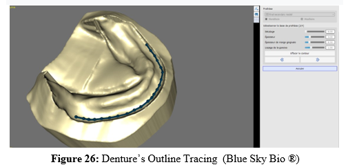
Gingival Sculpting and Finishing
After tracing the outline of the denture, the software automatically adds the false gum from the chain of teeth to the base of the model. However, gaps and excesses may be observed, which must be corrected by clicking on the "Add/Remove" box, while over-contours are corrected by selecting the "Local Deformation" box. Finally, the external surface is adjusted by clicking on the "Smooth" box. The size and strength of the instruments used are chosen by scrolling through the relevant sliders (Figure 27). In the next step, the software offers the user the option of connecting the prosthetic teeth and generating a reduction guide. .
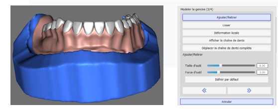
Figure 27: Finishing and Schulpting of the Denture Base (Blue Sky Bio ®)
Exporting the Different STL Files to Manufacturing
Once the prosthetic design is complete, the "Export" command is selected, a panel including all the STL files of the different designed surfaces: the alveolar prosthetic base, the connected teeth, the complete prosthesis and the prosthetic tooth reduction guide (figure 28). Although the design is free, exports are chargeable ($25 per case), in fact the Blue Sky software website contains the export price list (figure 29).
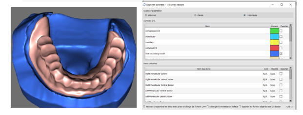
Figure 28: Different Designed Surfaces’s Export (Blue Sky Bio ®)

Figure 29: Blue Sky Bio ® STL Export Price List
Results
Mandibular Denture Computer-Aided Manufacturing
Presentation of the ASIGA MAX Printer
The "ASIGA Max" is the third DLP printer from Australian manufacturer ASIGA. This 3D printer was designed and engineered for dental and audiology laboratories. With its 62-micron XY resolution and 1-micron Z increments, it is the highest-resolution DLP 3D printer to date.
Its biocompatible certification allows it to print biocompatible materials approved for intraoral use. Thanks to its compact work area (119 x 67 x 75 mm) suitable for small work environments, its ergonomic interface, its touchscreen (Figure 30) displaying real-time print progress indicators, and its reliability based on the quality of its electronic and mechanical components, it remains easy to use; the presence of a single calibration point ensures at a single point, and the tank and resin changeover is rapid (less than 60 seconds).
Its SAS (Slide And Separate Technology) minimizes the retraction efforts induced by 3D printing processes, thus limiting the number of supports required. The unique Asiga SPS® process ensures that each model layer is precisely formed in minimal time, making it ideal for the manufacture of medical devices where precision is essential. The included software is designed for quick and easy print preparation with manual or automatic support creation. Furthermore, the software allows for all possible settings to be made to use all compatible resins on the market, as the printer is fully open to third-party materials. Finally, this printer has an Ethernet connection and Wi-Fi connectivity to easily start printing remotely [1].

Figure 30: ASIGA MAX 3D Printer[1]
|
Printer volume |
260x 380x 370mm³ |
|
Impression area |
119 x 67 x 75 mm³ |
|
weight |
17.5Kg |
|
Technology |
DLP (lumière UV LED) |
|
Interface |
Wifi, Ethernet, USB, Ecran tactile couleur |
|
DLP wavelength |
385 nm ou 405 nm au choix à la commande |
|
Electrique Tension |
110~240 V (50~60 Hz) 10A max |
|
Z Resolution e |
Incréments d’1 micron |
|
Thinner thickness «mu» |
75 microns |
|
Speed impression |
40mm en Z/heures |
|
materials |
Résines photosensibles |
|
Alimentation |
24 VDC |
|
power |
240W Maximum |
|
XY pixel size |
62 microns |
|
Precision |
62 µm |
|
Wave length |
UV LED 405 nm ou 385 nm |
|
Printer storage |
De 18°C à 28°C |
|
Incoming format |
STL –SLC |
|
Outcoming format |
STL -G code |
|
Compatibility |
Mac OS X –Windows7 |
|
Price |
12019 € |
Figure 31: Table Summarizing the Technical Characteristics of the Asiga Max Printer
« Dentona Optiprint » Resin Presentation
We used "Dentona Denture" resin to create the base of the complete denture, while we opted for "Dentona Teeth" resin for the tooth impression (Figure 33). This resin is permanent, light-curing, biodegradable, and non-cytotoxic. The following table lists all its chemical and general characteris


Figure 33: « Dentona Optiprint » Resin
|
Chemical composition |
Bisphénol A-ethoxylat (2 EO/Phénol) Di méthacrylates |
|
DLP polymerization wavelength |
385 nm / 405 nm |
|
General presentation |
Liquide |
|
Density |
1,1g/cm3 |
|
Certifications |
Matière micro-remplie Certifiée CE de classe IIa Approuvée par la FDA |
|
Approuvée par la FDA |
|
|
Traction resistance (mPa) |
30 N/mm2 |
|
Elongation at break(%) |
2-3 |
|
Flexion resistance (MPa) |
85-100 |
|
Modulus of elasticity(MPa) |
2400-2600 |
|
Water sorption |
18.1 (μg/mm3) |
|
Water solubility |
5 (μg/mm3) |
|
Vickers hardness |
25 |
Figure 34: Table Summarizing the Physicochemical Characteristics of the “Dentona Optiprint” Resin
Impression of the Resin Alveolar Prosthetic Base
After importing the STL file of the resin honeycomb base into the “Composer” software, we first centered it on the printing plate, then we added support rods attached to the prosthetic intrados so as not to affect the final printing quality; The printing precision being 25µm, the duration of the latter was 5h47min (figure 35).

Figure 35: Preparation of the Denture Base for Impression
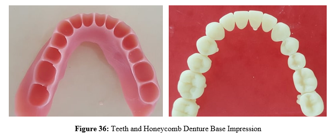
Teeth and Denture base Assemblage
The teeth and denture base were immersed in an isopropyl alcohol bath for 40 minutes to remove residual monomer and mattify the surfaces of these prosthetic elements. The supports were removed and then polished in the laboratory.
The teeth were bonded to the denture bases as follows:
• Application of 3M Auto-bond self-etching adhesive to the heels of the teeth and the denture base sockets.
• Light-curing for 40 seconds.
• Application of "Dontona Denture" resin to the sockets.
• Placement of the teeth and removal of excess resin.
• Light-curing for 40 seconds per tooth.

Figure 37: Denture Assembled
Post-Processing and Finishing
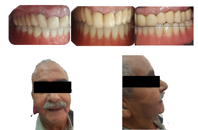
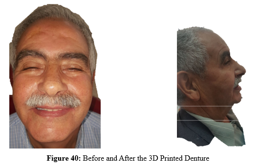
Post-treatment consists of placing the assembled denture in a 12 W UV chamber for 1 hour to complete the photopolymerization of the bonding resin; finishing consists of applying the “OPTIGLAZE” surface resin to both the intrados and the extrados of the denture, followed by photopolymerization for 60 seconds.


Figure 38: Mandibular Denture After the
Discussion
The advantage of the intraoral scanner compared to the classic mucostatic primary impression is firstly the time saving (2 min for the maxillary and 5 min for the mandibular arch on average) against (2 min for the tray selection 30 s for the working time and 90 s for the setting reaction of the alginate 3 to 5 min for the plaster to which we add 10 min for the classic casting of the impressions and the creation of the base). In parallel with the time saving we also note the economy of the material used and the quality of the recorded surfaces (both in color and texture) which allows a better appreciation of the location of the ligament brakes and the future posterior joint [2]. Zhang .F et al conducted an in vivo study on the validity of measurements made from intraoral scans compared to those made on plaster casts, the results indicate that measurements based on direct optical impressions using intraoral scanners are clinically acceptable and can replace primary and preliminary plaster models [3].
G.K.Sason and colleagues conducted a study to evaluate and compare the accuracy of direct intraoral and extraoral digital impressions (plaster cast from conventional alginate impression), in terms of "precision" and "accuracy" under in vivo conditions, and it was concluded that intraoral scanner showed less deviations, closer accuracy to real measurements and higher precision compared to extraoral scanner [4]. The in vitro study of "Il-Do Jeong" shows that digital impressions from intraoral scanners intraoral scanners with fixed acquisition [5].
Chen et al. compared conventional and digital methods (including FDM liquid deposition modeling) in the fabrication of mandibular individual trays, and the results showed that digital trays were more accurate than conventional ones; this may be explained by the post-polymerization shrinkage of the self-curing acrylic resins used to make conventional trays, which causes a gap between their intrados and the surface of the casts, especially at the peripheral edges and the post-dam joint, preventing the practitioner from achieving a correct peripheral joint, leading to reduced retention of the complete denture. Factors influencing the accuracy of FDM-printed individual trays using poly-lactic acid (PLA) filament are: CAD process discretization, material performance, nozzle width, temperature (both nozzle temperature and printer chamber or bed temperature), material extrusion and filling speed, layer thickness and deposition direction [6]. Sun et al conducted a study to evaluate the quality of secondary impressions made by 3D printed individual trays compared to conventional one (using a photo-polymerizable resin), then they evaluated the surface of the two different types of secondary impressions and their thicknesses; The results show that the secondary impressions made with 3D printed trays show a better distribution and a good thickness of the impression material compared to conventional ones, the use of stops showed no significant difference[7].


Figure 41: Photographs of the 3D Printed Individual Trays used (in red: Conventional , in white: 3D Printed )
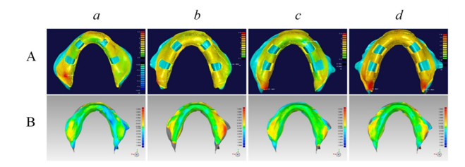
Figure 42: Material Thickness Analysis After Recording the Secondary Impressions According to the Individual Tray used (a and b: Conventional , c and d: 3D Printed )
Goodacre et al indicate that digital techniques offer a desirable balance between minimal manufacturing distortion and better fit, and that these computer-aided techniques are more accurate and reproducible than conventional techniques[8]. The use of high pressure and temperature for the fabrication of PMMA in digital prostheses contributes to the development of longer polymer chains than conventional PMMA self-curing resins, resulting in a higher degree of monomer conversion, less porosity, and reduced free volume. [9].
Although all digital dentures have a lower surface roughness and therefore offer smoother prosthetic surfaces compared to conven¬tional dentures, it has been proven that the surface roughness of milled digital dentures is superior to those produced by SLA or DLP, with lower porosity and better polishability; this is inherent to the milling process which produces fine lines and depressions of wavy surfaces, their size depends on the quality and size of the burs used [10].
Berli et al. demonstrated that water sorption of 3D printed resins significantly increases after thermal cycling, which reduces flexural strength and contributes to the increase in surface deterioration of these resins used in rapid prototyping processes[11]. The latter is inversely proportional to the filler content, in fact, 3D printed resins generally contain reduced inorganic filler particles; this is an inherent requirement of the 3D printing manufacturing process which stipulates that the viscosity of the resin must be kept as low as possible to facilitate material flow during the manufacturing process and also to achieve a good finished smooth surface. This reduced filler content also decreases wear resistance. Panagiotis et al. reported that if the adhesive is applied followed by the PMMA resin monomer, it acts as a sealant rather than a primer, thus increasing the chemical adhesion of the teeth to the bases[12].
Conclusion
The transition from traditional to digital dentures can take place at any stage of the work chain, however, it cannot be exempt from the secondary impression. In fact, and given its anatomical-functional character aimed at recording the play of the paraprosthetic organs, only the conventional method allows this objective to be achieved; Looking to future possibilities, it is not fanciful to imagine that in a few years we will see the development of new modules or software allowing the correct digitalization of this impression.
Statments
No funding declaration. informed consent was obtained from all subjects and/or their legal guardian(s)
Consent to Publish
The details/images will be freely available on the internet and may be seen by the general public.
Consent to Participate Declaration
Not applicable
Ethics Declarations
Not applicable
Authors Contribution
A : Treated the patient participated in the CAD-CAM workflow and achieved the denture insertion and follow up
B and C : Contributed to the CAM-CAM worflow helped during the 3D printing process ad itw as conducted in their private clinic
D : Contributed in the patient treatment as the head of removable prosthodontics department.
Competing Interests Declaration
No Competing Interests
Data Availability Statement
Data can be shared openly, No data are in a repository, No datasets were generated or analysed during the current study
References
- Andersson, M., Carlsson, L., Persson, M., & Bergman, B. (1996). Accuracy of machine milling and spark erosion with a CAD/CAM system. The Journal of prosthetic dentistry, 76(2), 187-193.
- Goodacre, B. J., & Goodacre, C. J. (2018). Using Intraoral Scanning to Fabricate Complete Dentures: First Experiences. International Journal of Prosthodontics, 31(2).
- Zhang, F., Suh, K. J., & Lee, K. M. (2016). Validity of intraoral scans compared with plaster models: an in-vivo comparison of dental measurements and 3D surface analysis. PloS one, 11(6), e0157713.
- Sason, G. K., Mistry, G., Tabassum, R., & Shetty, O. (2018). A comparative evaluation of intraoral and extraoral digital impressions: An: in vivo: study. The Journal of Indian Prosthodontic Society, 18(2), 108-116.
- Jeong, I. D., Lee, J. J., Jeon, J. H., Kim, J. H., Kim, H. Y., &Kim, W. C. (2016). Accuracy of complete-arch model using an intraoral video scanner: An in vitro study. The Journal of prosthetic dentistry, 115(6), 755-759.
- Chen, H., Yang, X., Chen, L., Wang, Y., & Sun, Y. (2016). Application of FDM three-dimensional printing technology in the digital manufacture of custom edentulous mandible trays. Scientific reports, 6(1), 19207.
- Sun, Y., Chen, H., Li, H., Deng, K., Zhao, T., Wang, Y., & Zhou, Y. (2017). Clinical evaluation of final impressions from three-dimensional printed custom trays. Scientific reports, 7(1), 14958.
- Goodacre, B. J., Goodacre, C. J., Baba, N. Z., & Kattadiyil, M. T. (2016). Comparison of denture base adaptation between CAD-CAM and conventional fabrication techniques. The Journal of prosthetic dentistry, 116(2), 249-256.
- Ayman, A. D. (2017). The residual monomer content and mechanical properties of CAD\CAM resins used in the fabrication of complete dentures as compared to heat cured resins. Electronic physician, 9(7), 4766.
- Srinivasan, M., Gjengedal, H., Cattani-Lorente, M., Moussa, M., Durual, S., Schimmel, M., & Mueller, F. (2018). CAD/ CAM milled complete removable dental prostheses: An in vitro evaluation of biocompatibility, mechanical properties, and surface roughness. Dental materials journal, 37(4), 526-533.
- Berli, C., Thieringer, F. M., Sharma, N., Müller, J. A., Dedem, P., Fischer, J., & Rohr, N. (2020). Comparing the mechanical properties of pressed, milled, and 3D-printed resins for occlusal devices. The Journal of prosthetic dentistry, 124(6), 780-786
- Lagouvardos, P. E., & Polyzois, G. L. (2003). Shear bond strength between composite resin and denture teeth: effect of tooth type and surface treatments. International Journal of Prosthodontics, 16(5).