
Journal of Applied Material Science & Engineering Research(AMSE)
ISSN: 2689-1204 | DOI: 10.33140/AMSE
Impact Factor: 0.98

Research Article - (2025) Volume 9, Issue 2
Aircraft Design for Safety in Emergency Landing
Received Date: Mar 21, 2025 / Accepted Date: Apr 18, 2025 / Published Date: May 09, 2025
Copyright: ©Â©2025 Yuri Spirochkin. This is an open-access article distributed under the terms of the Creative Commons Attribution License, which permits unrestricted use, distribution, and reproduction in any medium, provided the original author and source are credited.
Citation: Spirochkin, Y. (2025). Aircraft Design for Safety in Emergency Landing. J App Mat Sci & Engg Res, 9(2), 01-21.
Abstract
This article addresses the problem safety in emergency landing of an aircraft belonging to the category of transport airplanes. Emergency landing poses a significant challenge to the designers of such aircraft. In this case, the safety requirements aimed at avoiding serious injury to occupants (passengers and crew members) are combined with the uncertainty of the loads acting on impact with the landing surface and the behavior of the aircraft structure, the elements of which are destroyed during the impact. The provisions of airworthiness standards and existing design approaches mainly assume the conditions of a “soft” emergency landing (called a “minor crash landing”, corresponding to minor damage and injury), while in other possible scenarios the chances of survival of occupants are not guaranteed, and there is a safety deficit. To improve safety in this situation, a new aircraft design concept is proposed – Smart, Pro-Active, Resilient System (SPARS). It is applicable to the creation of various complex, safety-critical and expensive technical systems, the operation of which may involve extreme manifestations of uncertainty that exceed the design limits. The SPARS concept combines defense in depth against predictable hazards, in-service monitoring and diagnostics of anomalies with the ideas of a biologically similar (bionic) response of the system to adverse events, including unexpected ones, and giving it the ability to recover from destructive impacts. This article illustrates the SPARS concept using a hypothetical example of emergency landing of the Soviet aerospace vehicle 'Buran', similar to the American 'Space Shuttle'. However, the provisions presented are also applicable to conventional aircraft, including civil airplanes.
Keywords
Aircraft, Transport Category Airplane, Aerospace Vehicle, Emergency Landing, Design, Safety, Uncertainty, Defense in Depth, Structure Behavior, Neural Network
Introduction
Emergency landings of civil airplanes are rare, and each event of this kind not only attracts the attention of experts, but also causes public outcry, especially when it results in human fatalities. Two such disasters occurred at the end of 2024. On December 25, an Embraer 190 of Azerbaijan Airlines, flight 8243 from Baku to Grozny, crashed while landing on the ground near the city of Aktau in Kazakhstan. Of the 67 occupants, 38 died. On December 29, a Boeing 737-800 of Jeju Air, flight 7C 2216 from Bangkok, made emergency landing with the landing gear retracted at Muan Airport in South Korea and was completely destroyed. There were 175 passengers and six crew members on board. Only two survived. The possibility of emergency landing poses a serious challenge to aircraft designers. Airworthiness standards require that the designed structure ensure the safety of occupants in the event of a “minor crash landing”, i.e. an emergency landing which results in minor damage and injury [1-3]. However, the conditions of such a landing and the loads acting on the aircraft structure when it hits the landing surface in an abnormal manner are uncertain. The behavior of this structure, the elements of which are destroyed on the impact, is difficult to predict. Even if regulations and design approaches ensure safety in the particular case mentioned above, in many other possible scenarios the chances of survival are not guaranteed and there is a safety deficit. Recent accidents only confirm this regrettable judgment.
The shortcomings of the existing system of design measures to ensure safety in the event of emergency landing are even more clearly manifested in projects of aerospace vehicles such as the American Space Shuttle or the Soviet Buran. They were designed to transport astronauts, or cosmonauts, and large payloads into orbit and return them to Earth. On return, these vehicles flew in the atmosphere like airplanes, using aerodynamic surfaces (wings, rudders, ailerons, etc.). Such vehicles had the basic features of airplanes and were considered their most advanced type in technological terms1. Therefore, the design specifications for Space Shuttle or Buran corresponded to the requirements for transport category airplanes. Among the unclassified documents, the provisions closest to these specifications are contained in the Soviet airworthiness standards [4].
Since then, aerospace vehicles have been designed that also use aerodynamic surfaces during the launch phase into space. New shuttles are being developed for commercial orbital flights and suborbital transportation of people and cargo2. Over the past decades, the requirements for transport category airplanes in the countries that produce such airplanes have undergone some changes, but the essence of the regulatory approaches has remained the same. There is no doubt that when creating new generations of aerospace vehicles, their belonging to this category will be preserved and the continuity of specifications will be ensured. However, the range of potential payloads (cargo) necessitates an expansion of existing requirements – along with the safety of occupants, the integrity of particularly valuable or dangerous payloads (for example, containing toxic, flammable or radioactive substances) must also be ensured and environmental pollution must be prevented, bearing in mind the possibility of damage during an emergency landing.
Thus, even a preliminary analysis shows that there are safety issues in the event of emergency landing. They are associated with uncertainty of the aircraft structure behavior under conditions of partial destruction and the lack of safety guarantees in the entire range of possible emergency landing scenarios. These issues are inherited by new generations of airplanes and aerospace vehicles under design. In relation to the latter they are aggravated by the risks created by prospective payloads. Solving these issues in order to improve safety is a very urgent design problem. Intensive research and development (R&D) to improve safety in an aircraft emergency landing was carried out in the USSR during the creation of the Soviet space transport system Energia-Buran [5]. It was ceased with the closure of this program. The results of this work, as well as the state of subsequent R&D in the world, are described in the book [6]. The corresponding activities had formed a separate engineering discipline: crashworthiness. However, advances in this discipline over more than three decades have focused primarily on military helicopters and ground vehicles, particularly automobiles. They have not had a decisive impact on civilian aircraft or aerospace vehicles. There have been no significant changes in regulatory provisions or design practices to improve safety in emergency landing. This paradox can be explained, in the author's opinion, by
• Insufficient awareness of the problem of safety deficit in emergency landings against the background of relatively rare aviation accidents;
• Lack of breakthrough ideas aimed at ensuring safety;
• Relatively low technological level of solutions proposed within the framework of the crashworthiness concept.
It is reasonable to expect that recent catastrophic events with civil airplanes, as well as the new prospects for the development of aerospace transport, will attract the attention of regulators and aircraft manufacturers to the design case “emergency landing”. The article describes the continuation of the almost stagnant R&D on this topic and proposes to eliminate the safety deficit by applying a new design concept using a number of modern technologies, including a direction called “artificial intelligence”. To improve safety in emergency landing of an aircraft belonging to the category of transport airplanes, the Smart, Pro-Active, Resilient System (SPARS) concept is applicable. This concept appears to be one of the most effective tools for minimizing uncertainty at the creation of complex, safety-critical and expensive technical systems [7]. It uses the wellknown principles of multi-level protection, or defense in depth, against predictable hazards, as well as in- service monitoring of key operating parameters and diagnostics of anomalies in the system state. They are supplemented by ideas of bionic response to adverse events, including unforeseen ones, and recovery after extreme impacts leading to partial destruction.
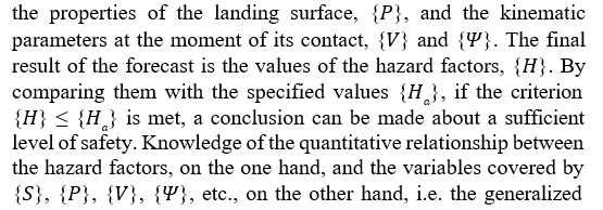
In Section 2 of the article, characteristic features of emergency landing of a transport category airplane are presented. These include its configuration before impact with the landing surface, the phases of the emergency landing process, hazard factors, etc. Section 3 provides an impartial assessment of the existing system of protection against hazard factors in the emergency situation under consideration by comparing it with the system used in another high-tech industry – nuclear power, as well as with the approaches adopted in military aviation. The assessment results point to weaknesses in protection and thus confirm the security deficit. Section 4 describes how the identified deficiencies can be addressed using the SPARS design concept. The functions of one of the main innovative components of this concept – the Critical and Emergency Control System (CECS) – are discussed. Section 5 is devoted to an important operation performed by this system in emergency landing – forecasting the behavior of the aircraft structure and evaluating hazard factors. To illustrate the forecasting, an example of a hypothetical emergency landing of the Soviet aerospace vehicle Buran is used. Based on the necessity to perform this operation by onboard electronic devices in real time, the most effective method of forecasting is the use of a neural network. Section 6 briefly outlines the implementation of the bionic aspects of the SPARS concept as applied to emergency landing.
Characteristic Features of Emergency Landing
As shown in Section 1, emergency landing is an important design case that must be considered when designing aircraft of all categories. Such a landing can be caused, for example, by birds entering the engines during climb, which leads to their shutdown [8], or by failure of the landing gear release system during descent [9]. When the engines stop working, there is little chance of returning to the departure airport or choosing another prepared landing strip. Therefore, pilots often make emergency landing on the nearest available land or water [10]. Contact of the wheels of the extended landing gear with uneven, loose, or marshy soil can result in beyond-design loads acting on the mechanism components, and their failure can cause serious damage to the aircraft structure [6, 11]. Although the best configuration for an airplane in emergency landing, including the position of the landing gear, is a subject of debate among professionals [12], regulatory documents provide for the retraction of the landing gear – see, for example, Code of Federal Regulations (CFR), Part 25 [1], § 25.561. Thus, one of the characteristic features of the case “emergency landing” should be considered the direct contact of the fuselage with the landing surface. This feature justifies the use of the slang term “belly landing”. It is important to note that emergency landing is not a design case for the fuselage structure3. The loads arising from contact may exceed the values allowed in design for normal operating conditions and cause destruction of structural elements. The combination of high inertial and contact loads in this situation determines the level of safety of people inside the aircraft and the integrity of the cargo being transported, as well as the potential harmful impact of destruction on the environment. Another characteristic feature of the emergency landings that are the subject of our analysis is the controllability of the aircraft, at least partially. The entire process of an emergency landing with these features – from the moment the pilot makes the decision to perform it until the complete cessation of movement of the landed (or ditched) aircraft – can be divided into three phases:
1) pre-landing control,
2) main landing impact and
3) post-impact processes.
Table 2.1 provides values characterizing the duration of these phases, as well as the corresponding safety tasks.
|
Phase |
Characteristic duration |
Safety tasks |
|
1. Pre-landing control |
Minutes |
Ensuring a ”soft” emergency landing |
|
2. Main landing impact |
From tens to hundreds of milliseconds |
Limiting the intensity of hazard factors |
|
3. Post-impact processes |
From seconds to one minute |
Counteracting dangerous post- impact processes |
Table 2.1: Emergency Landing Phases
Control in the first phase of emergency landing, preceding the main impact of the aircraft on the landing surface, is carried out by the pilot, based on the state of the aircraft (primarily the operability of its engines and aerodynamic surfaces), environment data and recommendations from air traffic controllers. The expected result of control is to bring the aircraft to a chosen landing surface, the characteristics of which, in combination with the kinematic parameters (landing velocity vector and rotation angles of the aircraft axes), can ensure a ''soft'' emergency landing.''Softness'' means avoiding fatalities, minimizing possible occupant injuries and aircraft damage. The first phase of emergency landing may also include touching down with less significant parts of the aircraft, for example, wings, to absorb excess kinetic energy by their destruction [12]. Thus, during emergency landing, several impacts are possible, but the main one is the impact of the fuselage, which is accompanied by the highest loads. Taking into account controllability in the first phase, emergency landing is sometimes called a ''controlled crashing''.
In the main landing impact phase (corresponding to the contact of fuselage with the landing surface and taking a fraction of a second), control by the pilot is impossible [6]. The hazard factors in this case are the following:
1. Maximum values of accelerations acting on passengers and crew members, as well as acceleration profiles over time, since they may exceed human tolerance limits;
2. Destruction of cargo and equipment attachment units under the action of inertial forces, which may cause uncontrolled movements of the torn off mass items with the threat of damage to the aircraft compartments and injury to people inside them;
3. Injuries to people during their uncontrolled movements caused by contact with interior elements of the cockpit or passenger cabin;
4. Deformations of the aircraft structure (relative movements of its parts), which can lead to a reduction in the life volume of the cockpit and passenger cabin or contacts of large-sized cargo with structural elements of the cargo compartment, and also complicate the evacuation of occupants;
5. Destruction of pipelines and tanks of the aircraft or transported cargo with flammable, toxic or radioactive contents, threatening fire, explosion and environmental pollution;
6. Destruction of fuselage elements, leading to the aircraft sinking in the case of emergency landing on water, or ditching.
The listed factors are counteracted by a protection system, which includes a number of barriers (levels), which can be combined with passive or active safety means. The task of the protection system is to limit the intensity of hazard factors to values that exclude fatalities, reduce injuries to occupants and damage to the structure.
Following the main landing impact, the aircraft slows down as it moves along the landing surface. This may be accompanied by such post-impact processes as continued deformation and destruction of structural elements, uncontrolled movements of occupants, cargo and equipment inside the compartments, and release of the contents of damaged pipelines and tanks. The intensity of these processes and the degree of their danger largely depend on the functioning of the protection system during the main landing impact. Post-impact processes are counteracted by safety equipment that performs the functions of protecting, as well as mitigation and localization of consequences. If emergency landing is accompanied by significant negative consequences in the form of human injuries and destruction of the aircraft, it is characterized as a ''crash landing''. The duration of the main landing impact phase is the shortest, but it is not only associated with the most intense manifestations of hazard factors, but also determines the requirements for control in the preceding, first phase, as well as the course and outcome of the subsequent, third phase. Despite the short duration of the second phase, it is this phase that has a decisive influence on safety during an emergency landing. This phase should be considered the most important for ensuring safety, and it will be the focus of our attention.
According to statistics, the frequency of emergency landings of civil airplanes is about 10-5 1/flight [13]. This frequency order corresponds to the boundary between low probability events (from 10-7 to 10-5) and moderate probable events (from 10-5 to 10-3) [2]. Such probability values cannot be neglected, especially since fatal consequences are not rare [12]. Therefore, regulatory documents used by global manufacturers of airplanes and airplane-type aerospace vehicles provide for the possibility of an emergency landing to be considered at the design stage [1-3]. Following the requirements of these documents, the designed aircraft must, despite damage during an emergency landing, ensure the relative safety of each occupant4. However, the conditions characterizing a relative safe, or ''soft'', emergency landing (properties of the landing surface, components of the velocity vector and rotation angles of the aircraft axes), which affect safety in addition to the structure parameters, are not clearly defined in the regulatory documents. The choice of these conditions remains with the pilot. It should be noted that due to the high speed of the accident development and the psychological pressure exerted on the pilot by the perceived threat of a catastrophic outcome see, for example, Airplane Flying Handbook [14], Chapter 18 not all aspects of the situation are within his control. The diversity of potential emergency landing scenarios, the behavior of the aircraft structure beyond its strength limits, and the variability of human operator actions (including errors and inaction) can hardly be foreseen and taken into account at the design stage. Also, the question of the applicability of the specifications given in the regulatory documents in quantitative form and based, obviously, on statistical data, to aircraft of non-traditional design and manufactured using new materials remains open [6]. Thus, the approaches currently used to ensure safety in emergency landing cannot be considered reliable: at the design stage, safety is ensured largely in form, but not in substance (which is shown even more clearly below), and at the operation stage mainly due to the qualifications of pilots, and only in the time interval preceding the main landing impact. This situation seems paradoxical and does not correspond to the current state of science and technology.
Assessment of the Existing System of Protection Against Hazard Factors in Emergency Landing
Assessment Methodology
The system of protection against hazard factors during an emergency landing of an aircraft is formed by physical (structural) barriers consisting of elements of the aircraft structure, in combination with safety systems (subsystems in relation to the entire system of protection), which come into action when these barriers are destroyed. The entire system of protection also includes measures carried out at all stages of the life cycle for the purpose of its effective functioning. The assessment of this system involves analyzing how it copes with the uncertainty inherent in a real situation and ensures safety. The assessment methodology is based on a comparison with the protection system used for nuclear facilities, which can be considered the most advanced. Safety of nuclear facilities, including nuclear power plants (NPPs), is ensured by multilevel protection (or defense in depth), considering the main expected hazard factor – ionizing radiation. This factor is countered by “a number of consecutive and independent levels of protection that would have to fail before harmful effects could be caused to people or to the environment” [15]. When one level of protection fails (one barrier is overcome), the next one comes into play. Properly organized multi-level protection ensures that no single failure due to technical malfunction or human error could lead to harmful effects and that a combination of failures threatening such consequences is of very low probability. A necessary aspect of defense in depth is the independence of the different levels. Safety can be assessed using various indicators, and the number of physical barriers in the path of a hazard factor, NB, is one of them – the higher the NB value, the higher the safety. In Russian NPPs with the most common type of reactor – WWER5– the following are considered as barriers [16].
1. Fuel matrix that prevents fission products from escaping under the fuel element cladding;
2. Fuel element cladding that prevents fission products from entering the primary coolant;
3. The boundary of the reactor coolant circuit, which prevents fission products from escaping into the volume under the hermetically sealed shell;
4. Hermetically sealed shell (containment) that prevents the release of fission products into the environment, and
5. Biological protection.
To assess safety on a probabilistic scale, each of these barriers should be assigned the probability of its failure Pi (i = 1, 2, … NB) or, conversely, the reliability value, Ri = 1 − Pi. Then we obtain the desired estimate in the form:
The reliability of physical barriers, taking into account the expected degradation of their properties during their service life, is substantiated using calculations and tests at the creation of a nuclear facility, and the actual properties are determined through in-service monitoring and diagnostics, thereby minimizing uncertainty. These, as well as other technical and organizational measures, form functional levels of protection that ensure [16,17]:
1. Prevention of deviations from normal operation, as well as failures of components important to safety, at all stages of the life cycle of a nuclear facility, starting with the design stage;
2. Detection of deviations from normal operation conditions using special systems and devices and an attempt to take the deviations under control in order to prevent the occurrence of accident conditions and return the facility to a safe state;
3. If it is impossible to control deviations, then preventing the development of an accident due to the inherent safety properties and (or) by engineered safety systems;
4. Management of a severe accident6 resulting from a failure of a previous level, using protective measures to mitigate its consequences and prevent further development threatening radioactive contamination;
5. Mitigation of the harmful effects of radioactive releases if they occur during a severe accident, including measures to protect personnel, the population and the environment.
Planning of the relevant activities at the design stage of a nuclear facility includes defining specific requirements for instrumentation. It must provide the human operator with the information necessary to determine the actual state of the facility during an accident, make decisions on accident management and post-accident analysis. However, the need for rapid operator intervention must be minimized, otherwise “it shall be demonstrated that the operator has sufficient time to make a decision and sufficient time to act” [17]. The number of functional levels of protection, NL, the number and physical parameters of active and passive safety systems, and (or) quantitative data of the inherent safety properties can be used, along with the values of NB and PB, as safety indicators for nuclear facilities. This entire set, combined with the advanced control, monitoring and diagnostic tools, as well as limitations on the manifestation of human factors, characterize nuclear power as a whole as a fairly safe industry [18]. This characteristic allows us to accept the defense in depth system developed and cultivated in to accept the defense in depth system developed and cultivated in this industry as a basis for comparison when assessing the system of protection in the event of emergency landing of a transport category airplane (and, accordingly, an aerospace vehicle).
Depth and Reliability of Protection
In the event of emergency landing of a transport category (civil) airplane, there are two physical barriers in the path of the accelerations that constitute the first group of hazard factors (see Section 2): the fuselage structure and the passenger or crew member seat equipped with restraining safety belts. The fuselage structure is not designed to withstand impact with a hard landing surface without the use of landing gear, so its behavior in emergency landing is a priori uncertain. However, the regulatory documents contain provisions on the role of this structure as a barrier. For example, the relevant relevant requirement of CFR [1], given in § 25.561, is reproduced in footnote 4 (see Section 2). This requirement is associated with the correct use of seats, belts and other safety design provisions, retraction of wheels and limitation of accelerations acting on an occupant to the specified maximum values, {amax}. Thus, in relation to the fuselage structure it is indirect. The requirements for a seat with restraining belts as a second physical barrier to resist acceleration are formulated in regulatory documents more clearly. In addition to specifying {amax}, these requirements define the details of the acceleration- time profile, {a(t)}, for which seats and belts must be designed and tested, establish occupant injury criteria, and specify the impact resistance values and structural features see, for example, CFR [1 § 25.562 and § 25.785.
Therefore, for the category of airplanes under consideration (which includes aerospace vehicles) the number of physical barriers that resist the first hazard factor can be estimated as NB(1) = 2 . However, there is uncertainty regarding the function of the fuselage structure as a barrier, and accordingly, its reliability in the event of impact with a hard landing surface is not determined. It should be noted that within the framework of the crashworthiness concept used in the design of military helicopters, a special energy- absorbing structure of the lower part of the fuselage is provided as the first physical barrier against impact accelerations [19–22]. The behavior of this part Severe accident is characterized by the failure of physical barriers with an immediate threat of release of radioactive substances into the environment. Is analyzed through calculations and experiments, which allows designers to minimize the mentioned uncertainty and obtain a sufficiently reliable first barrier.
The maximum acceleration values specified in the regulatory documents are based on experimental data from many years ago, presumably corresponding to the conditions of emergency landings of light airplanes. This hypothesis is supported by the ratios of ultimate acceleration components CFR [1], § 25.561:
ax max = 9g when the forces of inertia act forward,
ax max= 1.5g when they act rearward;
ay max= 6g when the forces of inertia act downward,
ay max= 3g when they act upward;
az max = 3g when the forces of inertia act sideward on the airframe, and (3.2)
az max = 4g when they act (sideward) on the seats and their attachments, where g is the acceleration of gravity; subscripts x, y and z denote the longitudinal, vertical and side components of the acceleration vector.
Emergency landings of light airplanes are characterized by a short stopping distance and possible impacts with trees, bushes or other small obstacles in order to reduce horizontal velocity, as well as frequent burying the nose in the soil [14], Chapter 18. These features determine higher values of longitudinal accelerations compared to other components. The extension of these data to transport category airplanes (heavy-weight and widebody), as well as to aerospace vehicles, the structure (in particular, the low curvature of the fuselage bottom) and the kinematic parameters during landing of which differ significantly from those of light airplanes, raises doubts. Thus, the maximum acceleration values specified in regulatory documents appear to be unfounded when applied to modern airplanes, especially of new types.
The second group of hazard factors – the destruction of cargo and equipment attachment units and possible subsequent uncontrolled movements of the torn off mass items – is countered by physical barriers formed by the attachment units themselves, the structure of the cargo compartment and restraining structural elements.
Regulatory documents set requirements for the strength of attachment units in the design case “emergency landing” so that the torn off mass items do not cause injuries to occupants, do not damage pipelines and fuel tanks, and do not impede evacuation. Strength requirements are expressed in terms of maximum values of inertial loads that the attachment units must withstand. They correspond to the maximum values of accelerations acting on occupants, {amax}, taking into account the wear of the attachment unit parts – see, for example, CFR [1], § 25.561. The structure of the cargo compartment and restraining structural elements, including locking doors, must maintain the load-bearing capacity under relevant loads and also perform the function of localizing the possible consequences of the detachment of mass items [1], § 25.787 and § 25.789 [1]. Thus, the number of physical barriers in the path of the second group of hazard factors is 3 (NB(2) = 3).
It should be noted that the expression of the requirements for the strength of the attachment units through the maximum values of accelerations, {amax}, neglect the effects caused by the dynamic properties of large-sized and heavy payloads. Their mass and stiffness of the structure can affect the dynamic response of the aircraft structure in emergency landing conditions and, accordingly, the required strength of the attachment units. The provisions of the regulatory documents leave unclear the conditions under which such effects should be taken into account, and this uncertainty aggravates the above-mentioned shortcoming of specifying the required strength using {amax}.
Injuries to occupants due to their uncontrolled movements during an emergency landing – the third group of hazard factors – are prevented by seats with restraining belts, the structure of which must resist deformation and destruction. The corresponding requirements are established in regulatory documents – see, for example, CFR [1], § 25.561, § 25.562 and § 25.785. The required strength of the structure is determined by the ultimate values of inertial loads, expressed, as in the previous two cases, through maximum value of acclerations {amax} consequently in relation to the third hazard factor, one physical barrier is provided, i.e. NB(3) = 1. The use of airbags was studied for military helicopters. They do not belong to physical barriers, but rather are one of the safety means that supplement the barrier function. The result of the study was the corresponding modernization of some types of helicopters [19]. The fourth group of hazard factors – deformations of compartments occupied by people or cargo – is resisted by the fuselage structure of the aircraft. As already stated above, for the fuselage of a transport category airplane, impact with a hard landing surface is not a design case, however, among the regulatory provisions there is an indirect requirement for the structure to perform the function of the first physical barrier. In addition, seats and mass items (including their attachment units) must not deform under loads not exceeding the specified limits (expressed in terms of maximum acceleration values in such a way that the deformations would impede rapid evacuation after an emergency landing [1], § 25.561. Quantitative limitations of deformations, or relative displacements of parts of the structure, {umax}, are not specified. The fuselage structure, structures of seats and mass items can be considered as three physical barriers preventing dangerous deformation, i.e.NB(4) = 3. It should be noted, however, that only those deformations that may impede evacuation are considered as dangerous, and other threatening changes in form are not mentioned in the regulatory documents. As a result, there is uncertainty regarding the life volume of the cockpit or passenger cabin, as well as the possible damage to valuable or dangerous cargo when contacting with the structural elements of the cargo compartment. This uncertainty is due to the a priori unknown behavior of the fuselage structure as the first physical barrier in an emergency landing on the ground.
The fifth hazard factor – the destruction of pipelines and tanks of an aircraft or transported cargo during a landing impact (which may pose a threat of fire, explosion and environmental pollution) – is countered primarily by their structure, which must have an appro- priate level of strength. Strength requirements are expressed, as in the previous cases, in terms of maximum acceleration values [1], § 25.561 [1]. If any pipelines or tanks may be damaged by mass items that were placed in compartments and torn off from their attachment units, then the structure of the corresponding compart- ment and the structure of the mass item, including the attachment units, act as potential additional barriers. Thus, the total number of physical barriers is in the range from 1 to 3 (1 ≤ NB(5) ≤ 3) ( In the framework of the Aircraft Crashworthiness Research Program (ACRP), the crash resistant fuel systems of transport airplanes and helicopters were investigated and the fuel containment concepts were tested [23]. The containment can act as an additional physical barrier. As a result of this work, the Advisory Circular 29-2B used for certification of helicopters has been updated in provisions relat- ed to the fuel systems resistant to destruction in landing impacts7. The sixth hazard factor – destruction of fuselage elements, leading to the aircraft sinking – applies exclusively to the case of ditching [1], § 25.563 and § 25.801. The fuselage structure, including exter- nal doors and windows, acts as a physical barrier to prevent rapid sinking and to allow occupants to evacuate. SoNB(6) = 1. Along with this hazard factor, in the case of ditching, other hazard factors discussed above may also come into play. The regulations provide for the investigation of behavior of the airplane “by model tests or by comparison with airplanes of similar configuration for which the ditching characteristics are known” (ibid, § 25.801).
The results of the assessment of the entire set of physical barriers that counteract the hazard factors that act during an emergency landing can be formulated as follows:
• Regulatory documents provide for such barriers in the aircraft design (although the term “physical barrier” is not used);
• The number of barriers, or levels of protection, varies from one to three depending on the hazard factor;
• These barriers are independent (in the sense that the failure of one does not lead to the failure of the other);
• The required properties of some barriers are not defined by regulatory provisions;
• The maximum acceleration values by which the requirements for other barriers are specified seem to be insufficiently founded when applied to new types of aircraft;
• As a result, the protection created by physical barriers is inferior in depth and reliability to the indicators typical for nuclear facilities;
• It is inferior in a number of indicators to the capabilities created by the crashworthiness concept, which is used in the design of military helicopters;
• The protection currently provided for transport category airplanes using physical barriers cannot be considered sufficient, since it does not ensure safety to the extent that is achievable with the current state of science and technology.
Functional Levels of Protection
Let us consider the functional levels of protection against hazard factors in emergency landing, which are formed by technical and organizational measures. It is obvious that the measures corresponding to the first level – prevention of deviations from normal operation conditions – are implemented at all stages of the aircraft life cycle. They include the use of reliable technologies for design, production, testing, maintenance and repair with high quality performance of all work tasks, certification of aircraft, licensing of operators (operating organizations and pilots) and compliance with operating rules. The second functional level of protection – detection of deviations from normal operation (normal flight) conditions using special systems and devices and an attempt to take the deviations under control – is implemented by automatic flight control systems, such as autopilot, the thrust control system, aerodynamic control surfaces, landing gear control system, etc 8. As soon as any of these systems identifies deviations from normal flight conditions, pilots receive warning signals and must take actions aimed at compensating for these deviations – see, for example, CFR [1], § 25.1585. The third level – measures taken when it is impossible to control deviations that prevent the development of an accident due to the inherent safety properties and (or) by engineered safety systems – are not defined in this form in airworthiness standards. The terms “safety systems” and “inherent safety” are not used in aviation. However, the ability of an aircraft to glide due to its aerodynamic quality in the event of engine shutdown can be considered an inherent safety property, and this property is of course used. In any case, preventing the development of an accident is the responsibility of the pilot: his actions in emergency situations are described in the airplane flight manuals (AFM) and pilot’s operating handbooks (POH) for particular airplane types. General recommendations can be found in Chapter 18 of the handbook [14]. When the pilot decides to perform an emergency landing, his subsequent actions constitute the content of the pre-landing control phase. Thus, the third functional level of protection for transport category airplanes is not technically developed and is implemented by a human operator. Control before contact with the landing surface must ensure contact conditions that will exclude fatal consequences, minimize possible injuries to occupants and other damage (see Section 2). What these conditions are in quantitative terms and what the consequences of their non-compliance might be remain generally uncertain. Note that in military aviation, when the pilot considers it impossible to make a “soft” emergency landing, he ejects. Ejection seats or crew escape capsules [6] can be classified as safety systems (active safety systems). The fourth level – managing an accident resulting from a failure of the previous level, using protective measures to mitigate its consequences and prevent a catastrophe – is associated primarily with the phase of main landing impact. In this phase, protection functions in the form of physical barriers, limiting the intensity of hazard factors to values that presumably exclude fatal consequences, reduce injuries and material damage (see Subsection 3.2).
The fifth functional level of protection, as applied to emergency landing, can be interpreted as mitigation of the harmful consequences of the destruction of the aircraft, including injuries to occupants, sinking of the aircraft in the event of ditching, fire, explosion and environmental contamination. This level is implemented in the phase of post-impact processes using intact physical barriers, structural elements and equipment that ensure the evacuation of passengers and crew members – see, for example, CFR [1], § 25.801, § 25.803, § 25.807, § 25.809 - § 25.813, § 25.815 and AC 25-17A, – and appropriate rescue measures. A summary assessment of the functional levels of protection against hazard factors during an emergency landing is as follows:
• Such levels are not defined in regulatory documents, but their equivalents can be found among the provided technical and organizational measures;
• The number of levels that are independent can be considered equal to 5, which corresponds to the depth of protection of nuclear facilities;
• The third level – measures taken when it is impossible to control deviations from normal flight conditions and preventing the development of an accident – is implemented, in contrast to the protection of nuclear facilities, not due to the inherent safety properties and (or) by engineered safety systems, but through the actions of the human operator (pilot) in the pre-landing control phase;
• The purpose of this control is to ensure emergency landing conditions that would exclude fatal consequences, minimize possible injuries to occupants and other damage, but the quantitative relationship between landing conditions and the values of hazard factors during the main landing impact is not determined;
• This uncertainty seriously complicates predictive safety assessment and accident management;
• In military aviation, in the event of failure of the third level of protection, the rescue of crew members in ejection seats or crew escape capsules is carried out, but for transport category airplanes such measures are not envisaged;
• Due to the weakness of the third functional level, caused by the above-mentioned uncertainty, the expected unreliability of human factors (embodied in the pilot) and the absence of automatic safety systems, the protection provided cannot be considered sufficient, especially considering the modern scientific and technical potential.
Assessment Totals
The assessments given in Subsections 3.2 and 3.3 demonstrate a certain logical coherence and relative completeness of the protection system formed by the requirements of regulatory documents regarding emergency landings of transport category airplanes. Fulfilment of these requirements at the design stage ensures safety within the limits considered acceptable by regulators. However, this protection is weaker in depth and reliability as compared with the defense in depth system used for nuclear facilities, which we have accepted as the most advanced achievement. Moreover, in a number of respects it is inferior to the crashworthiness concept adopted in military aviation. For transport category airplanes, the functional level of protection preventing the development of an accident using the inherent safety properties and (or) engineered safety systems is poorly developed. It is implemented in the pre- landing control phase due to the actions of the pilots. But the relationship between the emergency landing conditions (including the properties of the chosen landing surface and the aircraft kinematic parameters) that can be achieved by such control and the values of the hazard factors that are realized during the main landing impact is not quantitatively determined. It may exist in some form in the heads of designers or pilots, based on their professional skills. But this form is rather vague and not quantified.
The uncertainty of quantitative relationships between operating conditions causing extreme loads and the parameters of the mechanical system’s response to them is apparently generally inherent in emergency situations that are accompanied by nonlinear processes, including partial destruction. Due to the complexity of analyzing such processes, the complexity of the system itself, and the relatively infrequent occurrence of accidents, many of their types remain poorly understood to date. The consequence of this is uncertainty about safety in the event of a possible accident. The specification of maximum acceleration values for the case of emergency landing by regulatory documents can be considered as an attempt to partially solve this problem. However, it is not enough to limit only the mechanical response parameters that are hazard factors without relating them to the emergency landing conditions and other significant variables. It is necessary to know the relevant relationship in a detailed quantitative form in order to guarantee a certain level of safety by controlling the key variables. Such a possibility exists thanks to modern theoretical and experimental research methods, but it is not implemented in the design of transport category airplanes. The required properties of some physical barriers to hazard factors are not defined in regulatory documents or are not specified reliably enough. This makes it difficult to forecast the level of safety and ensure it in practice in the event of emergency landing.
The level of safety is negatively affected by the absence of active safety systems (including automatic ones), limited use of passive safety devices and the potential unreliability of human factors, embodied primarily in the pilot, who is subject to significant psychological pressure during an accident. Current approaches to the design of transport category airplanes do not provide for the need for rapid intervention by a human operator in accident management to be reduced to a minimum. The instrumentation currently used on transport category airplanes does not provide the ability to obtain all the information needed to determine the current state of the aircraft and to enable the pilot to make informed decisions on accident management. In particular, the pilot or the automatic control system does not have the data characterizing the actual properties of the structural elements that perform the function of physical barriers, as well as the properties of the potential landing surface, which are necessary for forecasting the behavior of the structure and the level of safety in emergency landing conditions and choosing the most acceptable combination of these conditions. In addition, the instrumentation available on board does not allow for a complete postaccident analysis of the aircraft’s state. This is not of decisive importance if the accident occurred in a populated and industrialized region, where such a service could be provided by a nearby specialized company. However, the instrumentation for the analysis in question is necessary in the case of a mission conducted in uninhabited areas or at a distance from Earth (if an accident occurs with an aerospace vehicle). The results of the assessment of the existing system of protection against hazard factors in emergency landing can be formulated as follows:
• This protection is characterized by a small number of physical barriers, uncertainty of the properties of some of them and unfounded requirements for others, uncertainty of the relationship between accident conditions and hazard factors, and underdevelopment of safety systems;
• All of the above indicates that safety is ensured in form, but not in substance, and this leads to a safety deficit;
• However, the safety deficit is not insurmountable – it can be minimized through R&D that must correspond to the current level of science and technology.
Potential of the SPARS Concept to Minimize Uncertainty and Safety Deficit in Emergency Landing
General Characterization of the SPARS Concept as Applied to Emergency Landing
The shortcomings of the existing system of protection against hazard factors in emergency landings of transport category airplanes, identified in the previous section, can be eliminated within the framework of the SPARS concept applicable in the design of new aircraft, including aerospace vehicles. This section presents its capabilities to minimize uncertainty and improve safety in this emergency situation. They enhance the potential inherent in traditional regulatory and design approaches. The SPARS concept incorporates safety ensuring methods corresponding to these approaches and supplements them with a number of innovations. Considering the diversity of possible causes of emergency landing, the many potential states of the aircraft structure and systems, the variability of the pilot’s actions, the wide range of landing conditions, as well as the insufficient study of nonlinear processes of deformation and destruction of the structure under impact loads, it is obvious that at the design stage it is impossible to foresee all possible scenarios for the development of such accident and assess their outcomes. In this case, designers are dealing with a combination of aleatory and epistemic uncertainty. The application of the SPARS concept is aimed at minimizing uncertainty and compensating for the safety deficit by giving the aircraft qualities that allow it (as a smart technical system) to assess emerging, including previously unknown, dangers in real time and respond to them with minimal negative consequences.
An emergency landing can be considered as the result of the transformation of a critical situation that arose in flight, which could not be prevented, into an accident, which in turn threatens to develop into a catastrophe. The capabilities of the SPARS concept to manage this transformation and prevent catastrophic development are realized through:
• Determining the quantitative relationship between the conditions characterizing an emergency landing and the hazard factors that arise in this case;
• Improving the physical barriers that counteract these factors;
• Using safety systems and other safety means;
• Using the Critical and Emergency Control System (CECS).
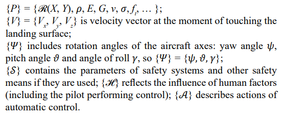
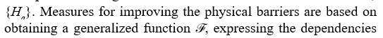
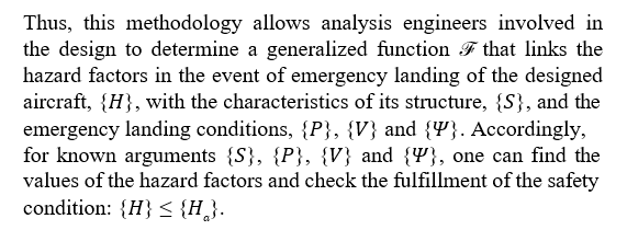
The hazard factors that arise in an emergency landing, {H} = {{amax}, {umax}, … }, can be expressed as a generalized function:

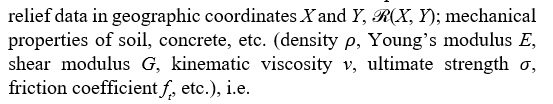
where {S} is the set of characteristics of the aircraft structure and its cargo, including configuration, dimensions, mechanical properties of structural materials, etc.; set {P} covers the landing surface parameters that affect the behavior of the aircraft structure when it impacts that surface:
According to the SPARS concept, the design specifications of the aircraft must contain allowable values for all hazard factors, {Ha}.

determined by analytical functions, tables, algorithms based on a numerical model, or other mathematical objects. The possibilities of obtaining the dependencies of hazard factors on the arguments {S}, {P}, {V} and
![]() are considered in Section 5.
are considered in Section 5.
The set {S} includes as a subset the characteristics of physical barriers, {SB}. The type of technical system limits the possible number of such barriers. For aircraft, it is problematic to increase it to values achievable in nuclear power plants or other ground facilities. Additional barriers make the aircraft heavier, and this may be unacceptable according to the criteria of weight optimization. The possibilities provided by the SPARS concept in this regard are discussed below in Subsection 4.2.
The insufficient depth of protection due to the limited number of physical barriers can be compensated for by using safety systems and other safety means. Their parameters, expressed in Eq. (4.1) through the argument {S}, are capable of having a significant positive effect on safety in emergency landing. Subsection 4.3 introduces some ideas being developed in this direction within the SPARS concept.
An important area of improving safety at the design stage is the implementation of CECS in order to prevent the development of critical and emergency situations or minimize their negative consequences. It should become part of the integrated flight control system (FCS or IFCS – see footnote 8), the task of which is to automatically process data characterizing the development of such situations in real time and to generate appropriate control commands. As for emergency landing, this system should minimize the pilot's involvement in emergency management. His involvement relates mainly to the pre-landing control phase and it is a potential source of uncertainty that can negatively affect
Improving the Physical Barriers
As shown in Section 3, the hazard factors in an emergency landing of a transport category airplane are counteracted by a relatively small number of physical barriers. The regulatory provisions leave the properties of some of them undefined, and the requirements for others, specified by maximum acceleration values, appear to be unfounded. In particular, the reliability of the fuselage structure as the first physical barrier on the impact with a hard landing surface is not determined and is a priori uncertain. To minimize uncertainty and ensure safety in this event, the SPARS concept includes improvements to the fuselage structure. Its lower part, which comes into contact with the landing surface, must have the properties of controlled (programmable) destruction and absorption of a certain amount of kinetic energy. Deformations of other parts of the fuselage must be within such limits that during an emergency landing the life volume of the cockpit or passenger cabin is preserved and valuable or dangerous cargo (payload) is not damaged due to not allowable contacts with structural elements of the cargo compartment (payload bay). These requirements correspond to the principles of crashworthiness incorporated into the SPARS concept. Their fulfillment must be confirmed by calculations and experiments at the design stage of the aircraft.
The SPARS concept involves substantiating the maximum values of accelerations, {amax}, which determine the required properties of other physical barriers including (see Subsection 3.2):
• passenger or crew member seat with restraining belts;
• cargo (payload) and equipment attachment units;
• cargo compartment (payload bay) structure; • restraining structural elements that prevent movements of the torn off mass items;
• structures of pipelines and tanks of the aircraft or cargo (taking into account the threat of fire, explosion and environmental pollution in the event of their destruction during the landing impact).
Along with a more founded specification of maximum acceleration values, the SPARS concept provides for considering the influence of the mass of large-sized and heavy payloads, as well as their structural stiffness parameters, on the dynamic response of the aircraft structure during an emergency landing. When such influence is significant, the requirements for the loadbearing capacity of attachment units and structural elements of the payload cannot be established using a priory known values of maximum acceleration values at its center of gravity. The strength of these units and structural elements must be substantiated by dynamic analysis of the mechanical system including the aircraft and the payload, an appropriate experiment, or another equivalent procedure covering the entire system. The complete set of requirements for the resistance of physical barriers must be expressed through the allowable values of the hazard factors,
between the conditions of emergency landing and the hazard factors (see Subsection 4.1). Being known, these dependencies allow designers to determine the characteristics of the barriers, {SB}, at which the hazard factors do not exceed the allowable values with the expected values of other arguments of the function 
In Subsection 4.1, the problem of increasing the number of physical barriers due to the limitations imposed by weight optimization was mentioned. For example, adding a second, internal shell to the fuselage structure, thus creating a passenger or cargo compartment in the form of a capsule inserted into the outer shell would help improve safety in the event of emergency landing. But the price for this would be an increase in the mass of the aircraft, with a simultaneous increase in the required engine power and fuel consumption per flight. Detailed studies are needed to substantiate the effectiveness of such measures. Given such limitations, a protective shell for fuel system components seems to be the only unconditional candidate for the role of an additional physical barrier. It can be comparatively compact and light. Studies in this direction conducted earlier [22] deserve to be continued within the framework of the SPARS concept. A reasonable alternative to installing additional barriers is to improve the properties of existing ones. In particular, the resistance of structural elements to impact loads can be increased by manufacturing them from meta- materials that can change their physical and mechanical properties under high-speed loading in such a way as to absorb significant kinetic energy at small relative displacements – see, for example, publications [25, 26].
Safety Systems and Other Safety Means
In conditions where there are few physical barriers to the hazard factors acting in emergency landing, and where the structure has limited resistance to extreme loads, some of the functions aimed at minimizing harm can be performed by safety systems and other safety means. The SPARS concept envisages equipping an aircraft with safety systems whose functions are similar to those used at NPPs: a controlling safety system, a protecting safety system and a localizing safety system [16]. The controlling safety system is activated at the end of the pre-landing control phase when CECS determines that some of the emergency landing conditions (properties of the landing surface, the aircraft velocity vector or the rotation angles of the aircraft axes) do not ensure the required level of safety (corresponding to the allowable values of the hazard factors,{Ha}). Due to the short time for decision-making and in order to minimize the uncertainty associated with the actions (or inactions) of the pilot, the activation and work of the controlling safety system must be carried out automatically. To increase safety in an emergency landing, it may be necessary to avoid the aircraft colliding with random obstacles on the landing surface, further reduce the vertical velocity, or change one of the angles. When control by aerodynamic surfaces cannot be relied upon, small solid-fuel rocket engines installed in certain places of the aircraft can be used as actuators of the controlling safety system. Their prototypes can be those used for ejection of pilots of military aircraft and helicopters or for ensuring soft landings of the Soviet reentry ballistic-type capsules Vostok, Voskhod and Soyuz.
The protecting safety system prevents uncontrolled movements of occupants or torn off mass items during the main landing impact and post-impact processes. It must come into action if the control in the first phase of an emergency landing, including work of the controlling safety system, failed, as well as in the event of failure of physical barriers such as seats with restraining belts, attachment units of the mass items, or structural elements of the cargo compartment that prevent the movement of the torn off items. The action is initiated by CECS, which identifies pre-landing control failure and (or) barrier failures. A possible implementation for the protecting safety system is to fill a part of the volume of the cockpit, as well as the passenger or cargo compartments, with foam, which can quickly acquire elastic properties [27]. This system can help maintain the life volume of the compartments occupied by people, and also perform a localization function, stopping the movement of the torn off cargo within the cargo compartment. In general, the localization function is associated with limiting the spread of flammable, toxic or radioactive substances released from destroyed pipelines and tanks. It is carried out by a localizing safety system, which starts working on a command of CECS and compensates for the failure of the physical barrier formed by the structure of the pipeline or tank containing the hazardous substance, and in the case of using a protective shell – this additional barrier (see Subsection 4.2). All three safety systems considered are active safety systems in the sense that they function when energy is supplied to them from some source. The initiation of the work of each of them is part of the automatic control actions,
![]() and it is provided by CECS.
and it is provided by CECS.
Along with active safety systems, passive safety means (or devices) can also be used, working on the basis of natural action, without additional energy sources, in particular, under the inertial forces. The range of passive safety devices include programmed destructible elements built into the load-bearing structure that limit the loads transmitted to other critical parts, such as passenger or pilot seats. Elements of this kind comply with the crashworthiness principles integrated into the SPARS concept. The development of safety systems and other safety means is an important area of R&D in the design of advanced airplanes and aerospace vehicles and one of the distinguishing features of the SPARS concept. The required parameters of these systems and means, {S}, must be determined based on the allowable values of the hazard factors, {Ha}, and the
![]()
– values of other arguments of this function (see Subsection 4.1).
Critical and Emergency Control System
The system described below, CECS, is intended to support the aircraft control process, taking into account the possibility of a critical or emergency situation occurring in flight, which may transform into an accident. Some of the CECS functions are implemented under normal flight conditions in order to recognize early signs of a critical situation and the approach of an emergency situation, as well as to prevent further negative developments. If such prevention fails, then other functions come into play to ensure accident management – as far as this is possible. CECS uses sensors, communications and instruments that provide in- service monitoring of the aircraft’s flight conditions, the health of its structure and performance of its systems, and diagnosing anomalies in real time. A significant portion of the equipment and devices necessary for this purpose is already applied in modern advanced airplanes. The SPARS concept incorporates the relevant technical solutions and supplements them by some innovations. The implementation of this concept provides for interaction of CECS with other components of IFCS, including avionics.
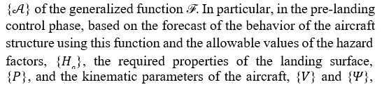
Part of the innovations associated with CECS consists of installing additional sensors to expand the range of recorded parameters. Innovations are also being introduced in the processing of information received from sensors. In particular, operations are being performed to eliminate fragmentation caused by gaps in data due to the absence of sensors at certain points on the aircraft or large time intervals between successive sensor records. Fragmentation is eliminated by reconstructing the fields of variables describing the environment surrounding the aircraft and the state of its structure and systems. Such reconstruction meets the ideas of information support for the life cycle of technical systems. This makes it possible to minimize the uncertainty associated with missing data and to recognize subtle signs of change that could lead to potentially dangerous deviations from normal operating conditions, as well as to detect hidden deviations. Operations on reconstruction, recognition of changes and deviations and assessment of the degree of their danger (including identification of a critical or emergency situation), determination of compensatory actions and analysis of their effectiveness, as well as other intellectual functions are performed by processor devices as part of CECS. The use of neural networks is envisaged for the implementation of a number of intellectual functions. In relation to small changes that have not yet reached the values that would characterize them as deviations, proactive (hazard-preventing) control is carried out – it corresponds to the subset of actions
<img src=" https://www.opastpublishers.com/scholarly-images/9104-68f7760f8ed4b-aircraft-design-for-safety-in-emergency-landing.png" width="500" height="100">
SPARS concept, both proactive and reactive compensatory actions should be carried out predominantly in automatic mode. In the event of an emergency landing that could not be prevented, CECS determines in real time control actions capable of minimizing the expected values of hazard factors (and thus the possible harmful consequences). They are also covered by the argument
are being found, which ensure that the allowable values are not exceeded. The required values {P} determined in this way enable the choice of an emergency landing site. This choice is being made on the basis of terrain information loaded into the TAWS (Terrain Awareness and Warning System) [28] and supplemented by data on the mechanical properties of the soil in the vicinity in its current state9 [24]. Based on the chosen emergency landing site (surface)
![]()
can be determined that ensure flight to this site and the appropriate touchdown conditions. When choosing the emergency landing site, it is also necessary to take into account the condition of the aircraft structure and systems, the availability of nearby airfields (where the rescue of people is facilitated by the presence of personnel, technical means and infrastructure) and weather conditions (wind, precipitation, visibility, the possibility of icing). The methodology for planning an emergency landing can be found, for example, in the publication [29]. It is implemented by a special component of IFCS – the emergency landing planner [30]. In the event of failure of the pre-landing control, i.e. the

ensure acceptable levels of hazard factors, the safety systems are activated (see Subsection 4.3). The controlling safety system is activated at the end of the first phase of emergency landing, and the protecting and localizing safety systems come into action in the second and third phases. In the main landing impact phase, CECS monitors the work of physical barriers and safety systems, records data on the behavior of the aircraft structure and systems, as well as hazard factors. If necessary, the localizing safety system is activated. Monitoring and recording continue during the post-impact processes phase. Some functions of CECS are also implemented after emergency landing. These include post- accident analysis of the aircraft condition based on data received from sensors and learning from the accident. The latter function includes replenishment and adjustment of the training set for the neural network used, taking into account newly obtained information. Among the many operations performed by CECS, an important one is the forecast of the behavior of the aircraft structure during an emergency landing (operation 8). The forecast is based on known structural characteristics, {s}, as well as input data on the properties of the landing surface, {p}, and the kinematic

of an emergency landing for a certain aircraft. Obtaining the dependencies expressed by this function is one of the key aspects of the safety providing methodology within the SPARS concept. Section 5 describes the determination of the dependencies in question using the example of a possible emergency landing of the Buran aerospace vehicle.
Determination of Structural Behavior and Safety Conditions in an Emergency Landing of the Buran Aerospace Vehicle
Dynamic Analysis
The behavior of the aircraft structure in an emergency landing can be determined by dynamic analysis using an appropriate mathematical model. This approach was implemented during the design of the Soviet space transport system Energia-Buran in the 1980s. The methodology of dynamic analysis applicable to the Buran emergency landing – hypothetical, but postulated in the design specifications – was absent at that time, and it was developed by the author [5].
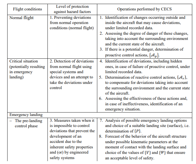
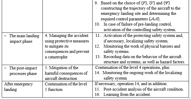
Table 4.1: Operations Performed by CECS in Relation to Emergency Landing
• Vibrations of its structure, payload and equipment;
• Large plastic deformations, changes in the shape of structural elements and their destruction under impact loads;
• Mechanical interaction of the fuselage with the landing surface.
These equations were obtained by mathematical modeling of a dynamic system that included the aircraft, the mass items attached to it, including the payload, and the solid massif adjacent to and forming the landing surface. For modeling, the finite element method was used in a physically and geometrically nonlinear formulation. The equations were expressed in displacement increments and solved by numerical integration over time using implicit methods. The developed methodology took into account the possibility of performing emergency landing on various landing surfaces with different mechanical properties: a concrete runway or soil with different ultimate strength values. The contact of the fuselage with the landing surface was simulated using special finite elements. For the case of landing on soil, their properties were assigned on the basis of experimental data accumulated during the experimental tests of landings of the Soviet reentry ballistic- type capsules. To study the features of the mechanical interaction between the bottom of the Buran fuselage (which has a low curvature) and the landing surface under conditions of a sliding impact – in order to describe these features in the mathematical model – a special experimental facility was proposed [31, 32]. The mathematical model had about 1800 degrees of freedom, which today seems like a very modest number, but for the computers of that time it was a serious challenge. Possible modeling errors caused by a course finite element mesh were compensated by refining the model parameters using experimental data. The model was validated by comparing the dynamic characteristics of the aerospace vehicle, obtained by solving the eigenvalue problem (eigenfrequencies and vibration mode shapes) for this model, with the results of horizontal frequency tests of the Buran flight specimen, in the cargo compartment of which the unit of auxiliary devices was located (see Figure. 5.1). The building of the model, calculation of dynamic characteristics and determination of the dynamic reaction of the structure in the main landing impact phase were carried out using a software system developed by the author and his colleagues, which was subsequently named NewTone [33].

Figure 1: The Buran Aerospace Vehicle with Payload (Payload Bay Doors Open)
In order to determine the behavior of the Buran structure and safety conditions for various emergency landing scenarios, many dynamic analyses (computer simulations) were performed corresponding to different values of the properties of the landing surface and the kinematic parameters of the aerospace vehicle. The range of scenarios studied was limited to cases of symmetrical landing, without lateral movement of the vehicle as a rigid body. In each dynamic analysis, the relative linear displacements of the elements of the spatial structure of the vehicle in the directions of three axes: x, y, z and rotations around them were considered. A number of computer simulations were carried out for different payloads of varying sizes and masses. As a result of each analysis, the time histories of the following parameters, characterizing the dynamic reaction (structural behavior), were determined:
• Components of the acceleration vectors at observed feature points of the structure, equipment and payload, {a(t)} = {a(t)} = {a1x (t), a1y (t), a1z (t), a2x (t), … anz (t)}10, which made it possible to estimate such a group of hazard factors as {amax};
• Internal forces in the attachment units of payloads with large dimensions and mass, {Q(t)}, on the basis of which the possibility of their destruction was assessed;
• Relative lateral displacements at points in the payload bay, {u1z(t), u2z(t), … }, to estimate deformations of its structure, {umax}, another group of hazard factors.
As an example, Fig. 5.2 shows the time histories of accelerations obtained by dynamic analysis of the emergency landing11 of Buran on the soil runway with the maximum allowable vertical velocity.

The design requirements for the strength of the attachment units for the Buran payload and equipment were essentially the same as those in use at that time for transport category airplanes: it was assumed that loads12 corresponding to the following range of accelerations act at the center of gravity of each mass item:
• For longitudinal load – from zero to 9g when load acts forward and from zero to 1.5g when load acts backward;
• For vertical load – from zero to 4g when load acts downwards and from zero to 2g when load acts upwards;
• For sideward load – from -2.25g to + 2.25g.
For payloads of 20 t and more, the maximum value of the specified longitudinal load acting forward was reduced to a value corresponding to 6g (similar Specifications were used in the development of the American Space Shuttle system). The comparison with the data given in Eq. (3.2) shows some differences between the regulations of that time and the requirements of modern airworthiness standards. However, these differences are not fundamental [4].
The results of dynamic analyses carried out during the design of the Energia-Buran system showed that loads on the attachment units of mass items do not exceed the specified limits if emergency landing of Buran is performed on:
• ![]()
velocity (at the moment of touch) approximately Vy = −1 m/s or
• The high-strength (e.g. frozen) soil or concrete runway (3.5 ≤
![]()
with vertical velocity about Vy = −0.7 m/s.
• The pitch angle (close to the angle of attack) must be maintained near the minimum allowable value (P = 9°).
Using computer simulations, the influence of the dynamic properties of large-sized and heavy payloads, errors in evaluating their dynamic response by acceleration shock spectra, and the stochastic spread of the bearing capacity of the collapsing structural elements on the forecast of behavior of the Buran structure and safety conditions during its emergency landing were also determined.
The developed methodology of dynamic analysis made it possible to:
• Consider at the design stage of an aerospace vehicle a set of hazard factors that act during emergency landing (and not just the impact accelerations specified in regulatory documents);
• Determine loads on equipment, payload and pilot seats, taking into account their placement, attachment features and partial dynamic characteristics, as well as structural parameters and dynamics of the vehicle itself (which represents an evolution of both regulatory provisions and traditional design practice);
• Assess how landing conditions that can be controlled in the time interval preceding the main landing impact affect loads and other hazard factors (which creates potential for emergency management).
In addition to its use at the design stage, this methodology is applicable to aircraft crash investigations, i.e. at the operation stage. An example of such an application was the dynamic analysis of the emergency landing (actually a crash) of the Mi-34 helicopter, carried out at the request of TsAGI13 [34, 35]. The methodology described can serve as a prototype for developing a more sophisticated theoretical approach to the design of new aircraft, including those with unusual configurations or manufactured using new structural materials. Improvements can also be aimed at analyzing safety conditions in a wider range of emergency landing scenarios and testing deeper defense against hazard factors. The finite element model required for a refined dynamic analysis that considers the subtleties of nonlinear deformation processes and destruction of structural elements of an aircraft when interacting with various landing surfaces will obviously include millions of degrees of freedom. The building of such a model is possible only at the final phases of design, when the entire set of characteristics of its structure, {s}, is known in detail. Dynamic analysis of one emergency landing scenario, even using modern high-performance computers, can take hours, and the computing resources required for multivariate analysis are correspondingly high. The time spent analyzing an emergency landing during aircraft design (or during a crash investigation) is certainly expensive, but it is not as critical as in-flight conditions, when an acceptable (from a safety perspective) option for performing an emergency landing must be chosen within a few minutes. Dynamic analysis is feasible at “ground conditions” and at a pace dictated by the available computing equipment, but it is practically inapplicable for forecasting the behavior of the aircraft structure and assessing safety in real time and with the resources available on board the aircraft, i.e. to perform operation 8 in Table 4.1. Thus, the methodology of dynamic analysis is not suitable for direct implementation into CECS, given its application in the event of emergency landing. To support control in critical and emergency situations – such as emergency landing – other forecasting methods are needed within the SPARS concept.
Response Surface Method
The above mentioned shortcomings inherent in the methodology of dynamic analysis can be overcome by turning to the method of approximate analysis of the behavior of structures using response surfaces. The response surface is a geometric representation of the response function – the dependence of a variable describing the response of a structure on the arguments characterizing the conditions under which this response occurs. In the case under consideration, a variable describing the response can be any of the
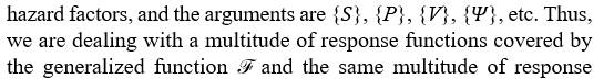
surfaces. The part of this multitude related to the maximum values of accelerations includes the following functions:
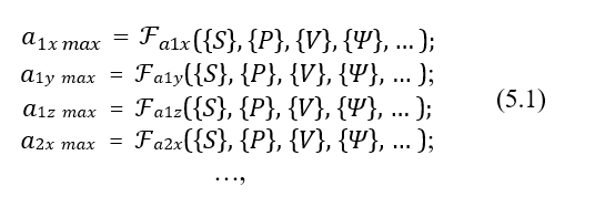
where the subscript numerical index at the maximum value of an acceleration component denotes the observed feature point of the structure, at which this hazard factor can reach a critical level. A response surface can be visualized only in the case of two arguments, and if there are more, it turns into a hypersurface that cannot be visually represented. The image of a hypersurface can be conveyed by a set of two- or three-dimensional geometric objects that are its “sections” for fixed values of a number of arguments. The study of emergency landing of Buran (briefly presented in Subsection 5.1) showed that, under the accepted scenarios for its implementation, an assessment of safety conditions is possible based on the maximum value of vertical acceleration at the center of gravity of the unit of auxiliary devices. For certain structural characteristics of the aerospace vehicle, {s}, and rotation angles of

maximum value of vertical acceleration at this point14, ay max, are

vertical velocity at the moment of its contact, Vy Thus, we arrive at the response function:
and a response surface that allows visualization – see Figure 5.3.


This response surface is built on the results of multivariate dynamic analysis in the following ranges of the Buran landing conditions:
the nodal values of the response function, and then linear interpolation between them was used to obtain the response surface. Despite the roughness of this interpolation, the resulting surface clearly represents the nature of the response function. If necessary, response functions can be determined in terms of other hazard factors and considering a larger number of arguments. In the latter case, the response surfaces lose the ability to be presented visually, but the important advantage of the described method remains. This advantage is that the response functions, even when they correspond to multidimensional hypersurfaces, allow one to quickly forecast the behavior of the aircraft structure and estimate the hazard factors during an emergency landing, {H}, with known characteristics of the structure, {S}, and expected values {P}, {V}
do not require large computing resources. The corresponding computational operations, mainly related to interpolation, can be performed by the on-board computer, providing substantiation for the choice of landing surface and kinematic parameters of the aircraft in real time. Tables containing the nodal values of the response functions and thereby determining the generalized

on dynamic analysis of a set of expected states of the structure (taking into account, among other things, various payloads) and emergency landing scenarios. If necessary, these tables can be adjusted and supplemented at the operation stage – immediately before the flight.
The response surface method is consistent with the principles of critical and emergency control that are fundamental to CECS, including its application to emergency landing. Thus, it appears to be very promising for implementation within the framework of the SPARS concept. However, implementation may be complicated by such features of the response functions as their non-smoothness or discontinuity, preventing the differentiability required for interpolation. These features can be related, for example, to the fact that structural characteristics actually vary in the range of possible values not necessarily in a smooth and continuous manner. In some intervals, they, as well as the values of other arguments of the response functions, may be completely absent.
The above difficulties can be overcome by using special mathematical techniques, in particular artificial smoothing and reconstructive filling of lacunae. At the same time, there is an alternative approach that is free from limitations of this kind. It is described in the Subsection 5.3.
Using a Neural Network
The development of artificial intelligence makes it possible to implement the principles of critical and emergency control, laid down in the SPARS concept, based on neural network technology. The idea of determining the dependencies between loading conditions and the response parameters of a structure in its actual state using a neural network was reflected in the regulatory documents of the nuclear industry, in the preparation of which the author took part [36–38]. This idea, combined with technical advances in recent years, has encouraged continued R&D in the area of emergency landing safety, which was interrupted by the closure of the Energia-Buran program
Below is presented the development of a neural network and the results of its experimental application at the first stage of continued work. The neural network was developed by engineer Igor V. Uspensky. He also prepared the training data set and processed the forecasts for the emergency landing of Buran. The objective of this stage, which can be considered a pilot project, was to:
• evaluate the accuracy of forecasting the behavior of the structure and hazard factors in emergency landing using a neural network;
• estimate the time required for its training and obtaining the forecasts (inferences);
• identify the advantages of the neural network approach compared to dynamic analysis (see Subsection 5.1) and the response surface method (see Subsection 5.2).
The neural network, developed considering the existing recommendations and experience from preliminary experiments, includes four layers, as shown in Fig. 5.4. The first layer, which receives input data, is formed by 80 neurons. The next two, inner layers contain 400 and 30 neurons, respectively. The output layer, from which the generated inferences are taken, is formed by one neuron. The neural network is implemented in the Python programming language using the open source software library TensorFlow (http://tensorflow.org).

Figure 4: Structure of the Neural Network Developed to Forecast the Behavior of the Aircraft Structure in Emergency Landing
To perform forecasts, the neural network must be trained on a set of known data characterizing the relationship between input and output. In the situation under consideration, this procedure

determined algorithm for obtaining inferences – output variables characterizing the dynamic response of the structure and hazard factors, depending on the input variables, i.e. the arguments of the function. The pilot project envisaged the network operating in several modes, differing in the number of input variables and the type of data sources. The training set for the main mode covered the variation of two input variables – the ultimate strength of

well as an output variable – the maximum value of the vertical acceleration at the center of gravity of the unit of auxiliary devices, ay max. The training was carried out using 475 examples generated based on the results of dynamic analysis of the emergency landing of Buran. The time spent on training, including data exchange with the cloud server hosting the software library TensorFlow, was no more than 15 s. The trained neural network performed forecasts of the values of ay max for 21

and Vy corresponding to the Buran emergency landing scenarios that were not included in the training set. The time to obtain the forecasts was about a second. The forecast results are presented in Fig. 5.5 against the background of the values found by dynamic analysis (see subsection 5.1). As can be seen from this data, the acceleration values generated by the neural network, despite their approximate nature, agree quite well with the results of dynamic analysis, which can be considered more accurate. For the considered emergency landing variants, the differences in the corresponding values do not exceed 4.53%. In a number of cases, the forecasted acceleration values turned out to be lower than those given by dynamic analysis. At this stage of the research, it is not yet clear whether such deviations are random or systematic.
In addition to the main mode, a modified option of the network operation was also tested – with the number of input variables increased to three due to the variable mass of the aerospace vehicle, which is part of the argument {S} of the generalized

based on the addition of the training set with the corresponding analytical law. In this way, the possibility of using data sources other than numerical arrays was assessed. The results obtained confirmed this possibility. A neural network similar to the one described can become part of CECS – for example, as software loaded into the on-board computer. The neural network training,

carried out at the pre-operation stages of the aircraft life cycle, including flight tests. The results of dynamic analyses obtained for a variety of assumed states of its structure and emergency landing scenarios are applicable as a training set. If necessary,before transporting cargo (payload) with previously unforeseen characteristics, additional training can be carried out. The range of training data sources can be expanded to include text, hypertext and graphical data. However, in this case, it is advisable to use a composite neural network that includes several branches, each of which specializes in a certain type of information. Then the generalized forecast result obtained in the output layer, where the branches are connected, will have a higher accuracy. In addition to forecasting the behavior of the structure and hazard factors during an emergency landing, the neural network approach is obviously applicable to performing other control operations in critical and emergency situations, listed in Table 4.1. This, like the other possibilities indicated above, should be tested in the course of further research.
Bionic Aspects of the SPARS Concept as Applied to Emergency Landing
The bionic ideas incorporated in the SPARS concept, as applied to the design of aircraft, including aerospace vehicles, cover:
• observation of the environment and the state of aircraft, which allows identifying changes occurring during the flight in terms of potential danger;
• preventive response to changes that may presumably lead to deterioration of normal flight

Figure 5: Neural Network Forecasts – Maximum Values of Vertical Acceleration, ay max, at the Center of Gravity of the Unit of Auxiliary Devices – In Comparison with the Results of Dynamic Analysis for a Number of the Buran Emergency Landing Scenarios
• detection of deviations from normal flight conditions, assessment of the degree of their danger and response in order to avoid the expected harm (reactive control);
• protection from hazard factors in the event of an uncontrolled development of an emergency situation;
• restoration (at least partial) of aircraft after an accident;
• learning from the emergency situation, or accident, to deal more effectively with similar events in the future.
The bionic nature of these ideas is expressed mainly not in the structural similarity of the created aircraft to any living organism, but in the reproduction of its behavior during extreme events. The SPARS concept primarily implements behavioral bionic principles. They are embodied in CECS. The operation of this system in case of emergency landing is described in Subsection 4.4. Its functions, presented in the list of operations in Table 4.1, should replace the actions of the pilot in a situation where possible negative manifestations of human factors – such as erroneous assessments and decisions, delayed reaction, stress or inaction – can lead to fatal consequences. As shown in Subsection 5.3, a number (if not most) of the control operations in critical and emergency situations can be effectively performed by a neural network. According to modern notions, this element of artificial intelligence functions like the brain of a living being, therefore, its application also reflects the behavioral bionic principles inherent in the SPARS concept. In the case of applying a neural network, learning from an emergency situation (operation 16 in Table 4.1) should involve supplementing the previously used training set with data from the performed emergency landing.
The possibility of restoring the aircraft after an emergency landing depends on the degree of damage to its structure, an adequate assessment of the damage, and the possibility of repairing or replacing damaged parts. The degree of damage of the structure is determined by the “softness” of the emergency landing conditions. Providing such conditions during the development of a real situation is part of the functions of CECS, which embodies, as indicated above, the behavioral bionic principles. Similar principles are implemented when this system carries out damage assessment – through post-accident analysis of the aircraft condition in accordance with operation 15 in Table 4.1. The ability to repair or replace damaged aircraft parts is linked to bionic principles not at the level of functions, but through the overall goal of ensuring a long life cycle. This goal is achieved through the properties of sustainability and recoverability, which correspond to the principles of resilient engineering, and the latter are incorporated into the SPARS concept. A description of how such principles can be implemented taking into account emergency landing is beyond the scope of this article. It is expected that this will be done in one of the author’s future publications.
Conclusion
This article demonstrates the potential of the SPARS design concept to minimize uncertainty and improve safety in an aircraft emergency landing. This potential is created through equipping the aircraft with more reliable physical barriers that limit the intensity of hazard factors, controlling, protecting and localizing safety systems, as well as an automated system supporting control in critical and emergency situations, CECS. An important function of the latter is to forecast the behavior of the aircraft structure and hazard factors in the first phase of emergency landing, preceding the main landing impact, in real time. As a result of the carried out research, it was founded that the most effective method of forecasting is the use of a neural network. A working prototype of such a network was created and its operation was tested during a pilot project.
The neural network approach is also applicable to other critical and emergency control operations. The study of this perspective, as well as the testing of other possibilities offered by the SPARS concept, is expected in subsequent stages of R&D.
References
- Code of Federal Regulations/Title 14/Chapter I/Subchapter C/Part 25 – Airworthiness standards: Transport category airplanes. (2024). https://www.ecfr.gov/current/title14/ chapter-I/subchapter-C/part-25
- Aviatsionnye pravila. Chast 25. Normy lyotnoi godnosti samolyotov transportnoi kategorii (Aviation rules. Part 25. Airworthiness standards for transport category airplanes), 3rd edn. (2009). Interstate Aviation Committee, Moscow (in Russian)
- Certification specifications for large aeroplanes (Amendment21). (2018). European Aviation Safety Agency, Brussels
- Edinye normy lyotnoi godnosti grazhdanskikh transportnykh samolyotov stran – chlenov SEV (Uniform airworthiness standards for civil transport airplanes of the Comecon member states). (1985). TsAGI, Moscow (in Russian)
- Spirochkin, Y.K. (1987) Metodika raschyota dinamicheskogo nagruzheniya gruzhov pri avariinoi posadke letatelnogo apparata (Method for analyzing dynamic loads on items of mass during an aircraft emergency landing). Dissertation. NPO Energia, Kaliningrad (now Korolyov), Moscow region (in Russian)
- Spirochkin, Y. (2023). Human factors and design. Springer,Singapore
- Spirochkin, Y. (2024, October 30). Towards minimizing uncertainty in the design of technical systems. ResearchGate. http://dx.doi.org/10.13140/RG.2.2.15766.15681
- Aviation Safety Network – ASN Aviation Safety WikiBase. (2019). https://asn.flightsafety.org/asndb/319362
- Sharma, S. (2024, May 13). Plane makes emergency landing without landing gear after circling for 4 hours in Newcastle airport drama. Independent. https://www.independent.co.uk/ travel/news-and-advice/newcastle-emergency-landingplane- airport-b2543941.html
- Aviation Safety Network – ASN Aviation Safety WikiBase. (2009). https://asn.flightsafety.org/wikibase/321581
- Joseph, C. (2012, September 16). Attention first-class passengers, this is your captain speaking... Crash test proves that it is much safer to sit in the back of the plane. Mail Online. https://www.dailymail.co.uk/news/article-2203888/ The-ultimate-crash-test-dummy-Whatpassengers-didnt-want- hear-safer-sit-back.html
- Rossier, R.N. (2016, April 2). Differentiating precautionary landings, forced landings, and ditching. AOPA | Emergency landings. https://www.aopa.org/training-andsafety/students flighttestprep/skills/emergency-landings
- Aircraft emergency landing. (2020, July 3). Aviation Nuggets | Blog. https://aviationnuggets.com/blog/30/aircraft- emergency-landing
- FAA-H-8083-3C. Airplane Flying Handbook. (2021).U.S. Department of Transportation, Federal Aviation Administration
- IAEA Safety Standards Series No. SF-1. Fundamental safety principles. Safety fundamentals. (2006). International Atomic Energy Agency, Vienna
- NP-001-15. Federalnye normy i pravila v oblasti ispolzovaniya atomnoi energii. Obshchie polozheniya obespecheniya bezopasnosti atomnykh stantsii (Federal regulations and rules in the field of atomic energy use. General provisions for ensuring safety of nuclear power plants). (2016). Federal Environmental, Technological and Nuclear Supervision Service of Russia, Moscow (in Russian) 33
- IAEA Safety Standards Series No. SSR-2/1 (Rev.1). Safety of nuclear power plants: Design. Specific safety requirements. (2016). International Atomic Energy Agency, Vienna
- Spirochkin, Y.K. (2019). Bezopasnost rossiiskikh AES s tochki zreniya inzhenera-mekhanika (Safety of Russian nuclear power plants from the viewpoint of mechanical engineer). SUPER Publishing House, Saint Petersburg (in Russian)
- Jackson, K.E., Fasanella, E.L. (2003). A survey of research performed at NASA Langley Research Center’s Impact Dynamics Research Facility. American Institute of Aeronautics and Astronautics, Reston, VA. https://www.researchgate.net/ publication/266370987
- Jackson, K.E., Boitnott, R.L., Fasanella, E.L., Jones, L.E., Lyle, K.H. (2006). A summary of DOD-sponsored research performed at NASA Langley’s impact dynamics research facility. Journal of American Helicopter Society, 51(1), 59-69
- Lau, S.T., Said, M.R., Yaakob, M.Y. (2012). On the effect of geometrical designs and failure modes in composite axial crushing: a literature review. Composite Structures, 94(3), 803–812
- Guida, M., Marulo, F., Abrate, S. (2018). Advances in crash dynamics for aircraft safety. Progress in Aerospace Sciences, 98, 106–123
- Frings, G. (1998, November 17). FAA Crashworthiness Research Program. International Aircraft Fire and Cabin Safety Research Conference. Atlantic City, NJ
- AC 29-2C. Advisory circular (with changes 1-9). (2023, June 23). Federal Aviation Administration. https://www.faa. gov/documentLibrary/media/Advisory_Circular/AC_29-2C_ CHG1-9.pdf
- Synbiosys. Material science. (2021). https://www.synbiosys. co/material-science
- Liang, X., Fu, H., Crosby, A.J. (2022). Phase-transforming metamaterial with magnetic interactions. Proc Natl Acad Sci, 119(1), 1–8
- IdeaConnection by Planbox. Civil aviation safety systems. (2015, May 17). https://www.ideaconnection.com/new- inventions/civil-aviation-safety-systems-09615.html
- FAA-H-8083-6. Advanced Avionics Handbook. (2009).U.S. Department of Transportation, Federal AviationAdministration. Updated May 2, 2013
- Meuleau, N., Plaunt, C., Smith, D.E., Smith, T. (2009). A comparison of risk sensitive path planning methods for aircraft emergency landing. ICAPS-09 Workshop on Bridging the Gap Between Task and Motion Planning (BTAMP), Thessaloniki, Greece
- Meuleau, N., Plaunt, C., Smith, D.E., Smith, T. (2009). An emergency landing planner for damaged aircraft. In Proceedings of the Twenty First Innovative Applications of Artificial Intelligence Conference. (IAAI-09), Pasadena, California. AAAI Press
- Spirochkin, Y.K. (1988) Iskhodnye dannye na provedenie eksperimentalnykh issledovanii parametrov reaktsii posadochnoi poverkhnosti s ispolzovaniem zhyostkikh maketov. Otchet P 26478-017 (Baseline data for experimental studies on the landing surface reaction parameters using rigid mockups. Report P 26478-017). NPO Energia, Kaliningrad (now Korolyov), Moscow region (in Russian)
- Patrushev, V.S., Pletnyov, I.V., Spirochkin, Y.K. (1989). Aviatsionno-kosmicheskii trenazhyor (Air-spacecraft simulator). Patent SU 1799479, 24 Nov 1989 (in Russian)
- Spirochkin, Y.K. (1993). Komp’yuternoe modelirovanie dinamiki konstruktsii pri avariyakh (Computer simulation of structural dynamics in accidents). Matematicheskoe modelirovanie (Mathematical Models and Computer Simulations), 5(6), 85–103 (in Russian)
- Lyakhovenko, I.A., Shenk, Y.V., Spirochkin, Y.K. (1989) K voprosu o vozmozhnosti chislennogo modelirovaniya avariinoi posadki vertolyota. Nauchno-tekhnicheskii otchet NTO 03-5942 (On the possibility of numerical simulation of a helicopter emergency landing. Scientific and technical report NTO 03-5942). TsAGI, Zhukovsky, Moscow region (in Russian)
- Spirochkin, Y.K., Shenk, Y.V. (1990). Chislennoe modelirovanie avariinoi posadki vertolyota (Numericalsimulation of a helicopter emergency landing). Problemy udara, razrusheniya i tekhnologii (Problems of impact, destruction and technology), 10(4), 62–63 (Publishing house VNITsUR-Resurs, Riga) (in Russian)
- SPiR-O-2008. Svod pravil i rukovodstv po opornym konstruktsiyam elementov AES s WWER (Code of rules and guides on supports for elements of nuclear power plants with WWER). Standard of organization. (2009). ENES, Moscow (Contributors: Evropin, S.V., Filatov, V.M., Golovlyov, Y.N., Obushev, A.E., Rodchenkov, B.S., Spirochkin, Y.K. et al.) (in Russian)
- OTT 1.5.2.01.999.0157-2013. Opornye konstruktsii elementov atomnykh stantsii s vodovodyanymi energeticheskini reaktorami. Obshchie tekhnicheskie trebovaniya (Support structures for elements of nuclear power plants with water- water power reactors. General technical requirements). (2013). JSC Concern Rosenergoatom, Moscow (Contributors: Spirochkin, Y.K., Obushev, A.E., Filimonov, S.V., Sorokin, A.N., Tarakanov, P.V. et al.). https://meganorm.ru/ Index2/1/4293736/4293736524.html (in Russian)
- VERLIFE. Guidelines for integrity and lifetime assessment of components and piping in WWER nuclear power plants. (2013). International Atomic Energy Agency, Vienna. Appendix F – Component and piping supports (Contributors: Obushev, A., Spirochkin, Y.)
Foot notes
1Aerospace vehicles may have design features related to their flight and the performance of specific operations in space, as well as re-entry into the atmosphere. However, from the perspective of safety in emergency landing, these features are insignificant.
2In aerospace flight, the terms “payload” and “cargo” may be synonymous.
3The exception is structural elements that contribute to ensure buoyancy in ditching (emergency landing on water), such as external doors and windows.
4In particular, in American airworthiness standards this requirement is formulated as follows: “The structure must be designed to give each occupant every reasonable chance of escaping serious injury in a minor crash landing” [1], § 25.561.
5Water-cooled Water Energetic Reactor corresponding to the international classification category “Pressurized Water Reactor” (PWR).
6Severe accident is characterized by the failure of physical barriers with an immediate threat of release of radioactive substances into the environment.
7The current version is 29-2C as amended on 23.06.2023 [24].
8In modern aircraft, these systems are included as components in an integrated flight control system (FCS). If the FCS is equipped with artificial intelligence elements, it is considered an intelligent flight control system (IFCS).
9The current state implies taking into account seasonal and average periodic meteorological variations
10The variable n used as a subscript denotes the number of observed feature points.
11From here on we mean a hypothetical but postulated emergency landing.
12Loads are understood as inertial forces.
13One of the largest research organizations in the USSR: “Tsentralnyi Aero-Gidrodinamicheskii Institut”. The current full name is the State Scientific Center – Federal State Unitary Enterprise “Prof. N. E. Zhukovsky Central Aerohydrodynamic Institute”.