
Advances in Theoretical & Computational Physics(ATCP)
ISSN: 2639-0108 | DOI: 10.33140/ATCP
Impact Factor: 2.6

Research Article - (2025) Volume 8, Issue 1
Magnetic Levitation, Based on the Weakening of the Effect of One of the Magnetic Fields on the source of another Magnetic Field when Two Magnetic Fields Interact
Received Date: Jan 02, 2025 / Accepted Date: Feb 12, 2025 / Published Date: Feb 27, 2025
Copyright: ©Â©2025 Dudarev V P. This is an open-access article distributed under the terms of the Creative Commons Attribution License, which permits unrestricted use, distribution, and reproduction in any medium, provided the original author and source are credited.
Citation: Dudarev, V. P. (2025). Magnetic Levitation, Based on the Weakening of the Effect of One of the Magnetic Fields on the source of another Magnetic Field when Two Magnetic Fields Interact. Adv Theo Comp Phy, 8(1), 01-04.
Abstract
The article discusses the device and method of creating an electromagnetic force having a strictly defined action vector. In conventional electromagnetic suspensions, the magnetic field created by the electric charges of one conductor acts on the electric charges of another conductor, while a force arises in it. The second conductor creates its own magnetic field, which acts on the charges of the first conductor and creates a counteracting force. In this case, two acting opposite forces balance each other in the system under consideration. The proposed design separates the paths of propagation of magnetic fields in such a way that the opposing force does not arise and does not manifest itself inside the device in question, and the principle of operation of the emerging force and counteraction to it is not fulfilled.
Keywords
Magnetic Levitation, Acting and Opposing Forces, Non-Isotropic, Inhomogeneous Medium, Diamagnet and Superdiamagnet, Separation of Magnetic Flux Propagation Paths
Introduction
The device described below relates to the field of physics and electrical engineering, namely, to a method of creating an electromagnetic force having a strictly defined action vector. Electromagnetic suspensions that use the force of magnetic attraction or repulsion to create a holding force (magnetic cushion) are described in diagrams of maglev trains. In such circuits, the electromagnets that create the effect of an electromagnetic cushion are positioned so that when they interact, a gap is formed between the poles of a moving object (electromagnet) and a fixed short-circuited circuit of an electromagnet or a non-magnetic metal sheet made of aluminum or copper. This arrangement of electromagnets requires a large number of fixed magnets involved in the movement of a moving object, high energy consumption, and a complex control circuit for a moving object. The scheme described below is fundamentally different from the above design schemes. In conventional electromagnetic suspensions, the magnetic field created by the electric charges of one conductor acts on the electric charges of another conductor, and a force is generated in it. The second conductor creates its own magnetic field, which acts on the charges of the first conductor and creates a counteracting force. In this case, the acting and opposing forces are equal in value and balance each other in the system under consideration. The proposed design separates the propagation paths of the magnetic field lines of interacting conductors in such a way that there is no equality of forces inside the device in question, and the principle of equality of the resulting action-reaction force is not fulfilled. This statement contradicts a well-known law that was formulated when the concepts of the magnetic field had not even been formulated yet. For example, the Lorentz forces of Newton's third law do not hold. Only by reformulating it as the law of conservation of momentum in a closed system of particles and an electromagnetic field can its validity be restored.Newton's third law is a consequence of the uniformity and isotropy of space. The effect of the law has so far been considered for isolated cases of magnetic interactions in homogeneous and isotropic media and has rarely been considered for possible cases of interaction of magnetic fields in inhomogeneous and nonisotropic media. This study examines a design that represents such an inhomogeneous and nonisotropic medium.
Materials and Methods
The proposed design consists of two DC electrical circuits. The first electrical circuit includes, in the simplest case: a low-voltage power source that can be used as a unipolar machine that generates high currents at low voltages (in other designs, you can abandon the use of a unipolar machine and use DC sources that generate low currents); a switch; a connecting element. wires (tires); a rectangular conductor 4 made of a non-magnetic sheet with good conductivity (for example, copper), having insulation, located in the gap of the magnetic circuit of the second electrical circuit. Also, the first electrical circuit has its own magnetic circuit consisting of two small U-shaped magnetic circuits 6 and two vertical spreading magnetic circuits 5. The second electrical circuit in the simplest case includes: a DC power supply; a switch; connecting wires; an electromagnetic coil with a winding. The second electrical circuit also has its own magnetic circuit consisting of a U-shaped magnetic circuit 2 made of a 0.3-0.5 mm thick ferromagnetic material and two horizontally arranged magnetic circuits 5, which are adjacent on both sides to the insulation of a rectangular 2 conductor 4. Between the vertical and horizontal magnetic circuits of the two magnetic circuits there are gaps filled with a diamagnet or superdiamagnet, isolating the magnetic circuit of one electrical circuit from the magnetic circuit of another electrical circuit.
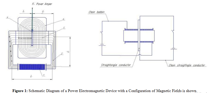
When isolating one magnetic core from another using superdia- magnetic insulation, it is desirable to make a vertical magnetic core from a material with the highest magnetic permeability, such as permalloy. This ensures a higher concentration of power lines in the vertical magnetic core and less impact on the insulation. When using a conventional diamagnet, it is necessary to make sure that the use of a material with high magnetic permeability for a vertical magnetic core does not lead to a "breakdown" of the dia- magnetic insulation and the propagation of magnetic field lines of the horizontal magnetic core through the insulation. Therefore, in this case, a material with high magnetic permeability should not be used for a vertical magnetic core.
The operation of a power electromagnetic device is carried out as follows: an electric current from a DC source entering the winding of coil 1 creates a magnetic field. The magnetic field lines of the electromagnetic coil are closed to each other through a U-shaped magnetic core 2, ferromagnetic pins of a horizontal magnetic core 5 and a rectangular conductor 4. An insulated rectangular conductor 4 through which a direct current J pr. flows. It is made of diamagnetic material with good conductivity. It is located in the gap between the terminals of two horizontal magnetic conductors, which are closely adjacent to its insulation. As a result, a current strength in amperes arises in the rectangular conductor 4. There are w turns in the winding of the electromagnet, and a current of J volts flows through them. We believe that there are no gaps between the touching parts of the sections of the U-shaped magnetic circuit, the horizontally expanding magnetic circuit and the insulation of the rectangular plate. Consider a generalized magnetic circuit, where sections are highlighted: section 1 (L1 , S1) of the magnetic circuit; section 2 (L2, S2) of the magnetic circuit; section 3 (L3, S3) of the magnetic circuit
(ferromagnetic contacts); section 4 (L4 , S4) of the magnetic circuit, the length of which is equal to the thickness of a rectangular conductor. Let's denote the average values of magnetic induction and magnetic field strength in individual sections of magnetic conductors and in a rectangular conductor, respectively: in section 1 – H1 and B1; in section 2 - H2 and B2; in section 3 - H3 and B3; in section 4 – H4 and B4. We neglect the scattering magnetic fields, so:
B1xS1 = B2xS2 = B3xS3 = B4xS4 = F1
According to the law of total current for the contour of the middle power line, we have:
H1xL1+2H2xL2+2H3xL3+H4xL4 =w x I ob., where: H=B/µ,
The equation can be written as:
(B1xL1 + 2xB2x L2 + 2xB3xL3) x k1/μ1 + B4xL4 /μ2 = w x I
ob. , where:
µ1 - is the magnetic permeability of the steel material in sections 1, 2, 3;
µ2 - is the magnetic permeability of the material at site 4;
k1 - is the filling factor of the steel material in sections 1, 2, 3;
S1 - is the cross-sectional area of section 1; 3 S2 - is the cross-sectional area of section 2;
S3 - is the cross–sectional area of section 3; S4 - is the cross– sectional area of section 4;
B1 – magnetic induction in section 1; B2- magnetic induction in section 2; B3 – magnetic induction in section 3;
B4 – magnetic induction in a rectangular conductor;
w - is the number of turns of the magnetization winding;
I ob. - this is the current strength in the magnetization winding.
From here we can find the value of the induction acting on a rectangular conductor 4:
B4 =(w x I ob – (H1xL1+2xH2xL2+2xH3xL3) x k1) x µ2/L4 The ampere force arising in this case in a rectangular conductor will be equal to:
F =B4 x I pr. x L , where:
F - is the ampere force in a rectangular conductor, B4 – magnetic induction in a rectangular conductor,
I pr. – the current strength in a rectangular conductor located in a magnetic field,
L - is the length of a section of a rectangular conductor located in a magnetic field.
The rectangular conductor 4, through which a direct current flows, also creates a magnetic field. The intensity and induction vectors of this magnetic field will have the form of closed concentric curved ovals relative to the conductor 4. The propagation of the magnetic flux lines of the conductor 4 will follow the path of least magnetic resistance, i.e. along the vertical gateways of the vertical magnetic conductor 5.
Results and Analysis
In a conventional design of an electromagnet with a conductor 4 in the gap of the magnetic circuit of the electromagnetic coil, the ampere force in the conductor 4 would be balanced by the force resulting from the action of the magnetic field of the conductor 4, which would act on the ferromagnetic domains of the magnetic circuit of the electromagnetic coil and the magnetic field of the electromagnetic coil itself. The magnetic field of conductor 4 would try to to expand the domains of the magnetic circuit of the electromagnetic coil in the opposite direction and distort the magnetic field of the electromagnetic coil 1. In the sections of the magnetic circuit and in the electromagnetic coil, there will be in this case, there would be a counteracting force balancing the Ampere force in conductor 4. For the above-described device, the influence of the magnetic field of the rectangular conductor 4 on the domains of the magnetic circuit of the electromagnetic coil and on the coil of the electromagnetic coil itself is significantly reduced (or even eliminated if used superdiamagnets) due to the fact that it is possible to maximally separate the propagation paths from two magnetic fluxes: the magnetic flux of an electromagnetic coil 1 and the magnetic flux of a rectangular conductor 4. This is achieved by isolating the propagation paths of their magnetic fluxes from each other. The insulation is carried out using diamagnets or, best of all, superdiamagnets. If, nevertheless, there is a slight effect on the domains of the magnetic circuit of the electromagnetic coil from the magnetic field of the rectangular conductor 4 (in the case of using diamagnets), then it will be significantly less than in a conventional electromagnet, since the magnetic field of the conductor 4 will propagate along the trajectory with lower energy consumption, i.e. through the magnetic tracks of the vertical magnetic circuit 5 and small Ushaped magnetic cores 6 of the magnetic core of the conductor 4 and will not fall into the magnetic core of the coil. Consequently, the Ampere force generated in the rectangular conductor 4 from the action of the magnetic field of the electromagnetic coil 1 on it will not be balanced by a force of the same nature, equal in modulus and opposite in direction in the electromagnetic coil from the action of the magnetic field of the conductor 4 [1-4].
Conclusion
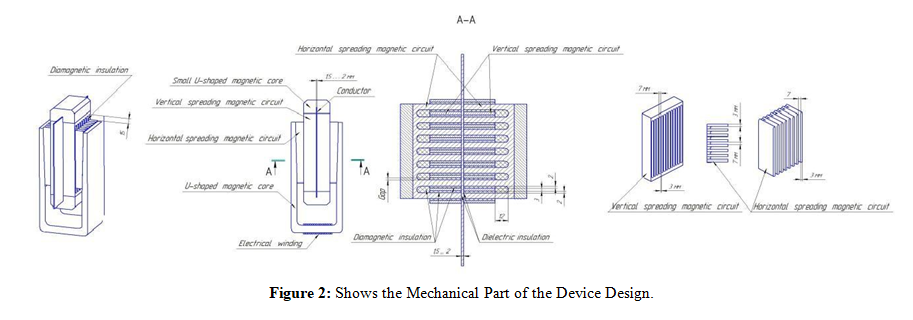
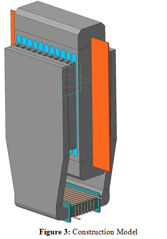
This study presents a simulation constructions and the device works to create a force vector of a certain direction. The results demonstrate that the proposed approach can be successfully implemented based on reducing or even complete exclusion of the influence of the magnetic field from one conductor to the source of another magnetic field , using breeding method distribution paths magnetic streams.
Literature
- Фейнман, Ð ., Ð?ейÑ?он, Ð ., & СÑндÑ, Ð?. (1978).ФейнмановÑкие лекÑ?ии по Ñ?изике. Рипол Ð?лаÑÑик.
- Тамм, Ð?. Ð?. (1929). Ð?ÑновÑ? Ñ?еоÑ?ии ÑлекÑ?Ñ?иÑ?еÑÑ?ва.
- De Jongh, L. J., & Miedema, A. R. (2001). Experiments on simple magnetic model systems. Advances in Physics, 50(8), 947-1170.
- Cullity, B. D., & Graham, C. D. (2011). Introduction to magnetic materials. John Wiley & Sons.