
Journal of Electrical Electronics Engineering(JEEE)
ISSN: 2834-4928 | DOI: 10.33140/JEEE
Impact Factor: 1.2


Research Article - (2023) Volume 2, Issue 4
Accurate and Fast Model for Single Rotor Double Stator Interior Permanent Magnet Brushless Synchronous Machine with Spoke-Type Structure At No-Load
Research Article J Electrical Electron Eng, 2023 Volume 2 | Issue 4 | 571
Ehsan Shirzad*
University of Bojnord, Bojnord, Iran
*Corresponding Author
Ehsan Shirzad, University of Bojnord, Bojnord, Iran.
Submitted: 2023, Nov 07; Accepted: 2023, Dec 04; Published: 2023, Dec 28
Citation: Shirzad, E. (2023). Accurate and Fast Model for Single Rotor Double Stator Interior Permanent Magnet Brushless Synchronous Machine with Spoke-Type Structure At No-Load. J Electrical Electron Eng, 2(4), 571-582.
Abstract
In this paper a 2-dimensional model by solving partial differential equations for single Rotor Double Stator Interior Permanent Magnet Brushless Synchronous Machine with Spoke-Type structure (SRDSIPMBSMWSTS) is formulated to predict flux density in air-gaps at only no load. After extracting relations are governing in each domain (magnetic potential vector and magnetic field intensity), boundary conditions between each two domain that are in adjacent to each other are applied to determine unknown coefficients. Output results are compared to finite element analysis (FEA) yield from Maxwell software to validate this fast and accurate model.
Keywords: Analytical Model, Finite Element Method, Sub-Domain, Boundary Conditions, Hybrid Electric Vehicle.
1. Introduction
The proposed machine has been of great interest in variable speed wind turbine generators due to the high efficiency of energy production (power) and low torque pulses And they are used in the hybrid car, also the most important advantages of the interior permanent magnet machine which made it necessary to conduct research on this machine are:
• High efficiency
• Long life and high reliability
• Hi h power de sity
• High resistance to demagn tization
• Robust and simple structure
• Low manufacturing cost due to s all volume
Structures with two stators or two rot rs or two stators and two rotors are so popular due to receiving energy from two sides and have high usage in industry [1]. Figure 1 shows a magnetic gearbox for a hybrid car. The researched machine for use n a hybr d car is stalled in suc a way that its outer rotor is connected to the ring gear and its inner rotor is connected to the sun gear, which causes the required torque to be transferred to the wheels at the desired speed. Another application of this car is in wind turbines in figure 1, which have the ability to produce energy simultaneously from two turbines. Figure 2 shows the placement of this type of machine for use in this system and permanent magnet switched flux machines with 2-way structure, which are shown in Figure 3, Figure 4, Figure 5 and Figure 6.
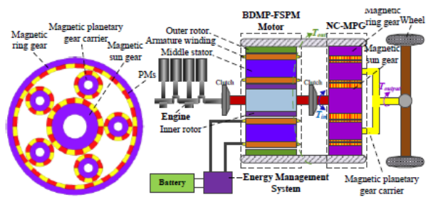
Figure 1. Gearbox system
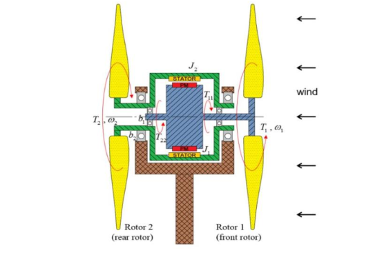
Figure 2. Wind Turbine
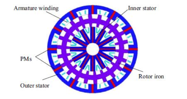
Figure 3. DSFSPM
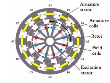
Figure 4. DEFESM
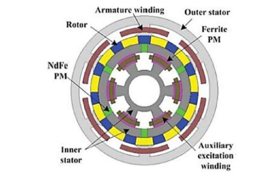
Figure 5. DSHEFSM
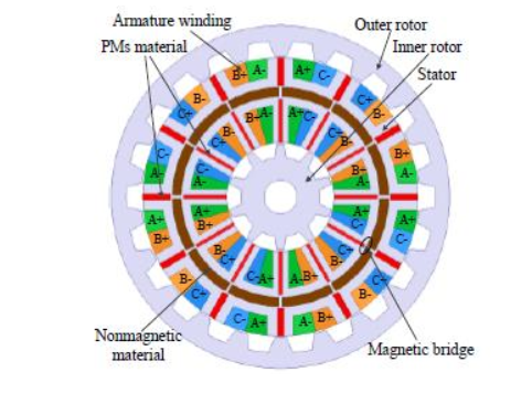
Figure 6. DSDRPM
Many works have been done so far that in two linear permanent magnet machines with two moving parts with different windings are used to calculate the quantities of induced voltage, thrust force, power pulses, vertical force and copper losses with the help of finite element method [7]. In a new structure from the point of view of winding (winding is a complete step and the magnets are located o the stator teeth) has been proposed for the permanent magnet machine and with the conventional structure in the torque quantities [8]. In the effect of current density, number of winding tur s and slot space for winding on the torque of permanent magnet machine is investigat d and the relationship between the torque and the outer radius of the rotor on the four permanent magnet machines is checked with the help of the finite element method [9]. In two examples of permanent magnet machine without stator yoke and two rotors have been proposed, and the effect of the number of poles and optimization variables on torque, torque pulses and machine speed has been seen, and the torque quantities, puls s Torque, induced voltage are calculated with the help of finite element method [10]. In a permanent magnet machine without bearing with combined winding is proposed and in two different structures in terms of the number of rotor and stator poles, a comparison between the quantity torque, magnetic flux density, iron and copper losses and suspension force are performed by considering the saturation limit and with the help of the finite element method [11]. In with the help of frozen permeability method and finite element method, a quantitative comparison is made between two single-stator and two-stator structures of the permanent magnet machine by considering saturation. After the superiority of the structure of two stators, a comparison is made between this structure with an internal magnet permanent magnet machine and a synchronous reluctance motor with a high permeability core, and the q antities of t rque, link flux in different currents are calculated [12]. For the permanent magnet machine for different structures, the amount of torque, suspension force, induced voltage, induced voltage harm nics and link flux are calculated wi h the help of the finite element meth d [13]. In two rotor permanent magnet switched flux machine with two designs Different types of stator winding are suggested (two types of centralized winding, parallel and series with agnets) and these two designs in terms of average torque quantities, torque pulses, flux distribution, induced voltage, link flux, torque ratio They are compared to the size of the magnet and the efficie cy, and they re compared with the single stator, single rotor switched flux machine of the internal rotor type [14]. In the external rotor permanent magnet flux-switched machine with concentrated-fractional winding is proposed and the quantities of torque, output power, induced voltage, induced voltage harmonics and link flux are calculated with the help of finite element method [15]. In the new structure of permanent magnet machine with two-stator is modeled with the help of finite element method and quantities of power pulses, average power, inductance, induced voltage and induced voltage harmonics are extracted [16]. In two single-phase permanent magnet two-stator axial flux machine is investigated in two models, in the first model, the two stators are completely matched, but in the second model, they have a spatial difference of 180 electrical degrees, and the analyzes are performed. Also, in order to increase the self-starting torque, the asymmetry in the air gap is done by cutting a part of the rotor, and finally, the quantities of link flux, induced voltage, tooth torque, average torque, self-starting torque are calculated with the help of the finite element method [17]. they become In a new structure for permanent magnet machine is proposed and with the conventional structure in the quantities of linked flux, induced voltage, induced voltage harmonics, tooth torque, average torque, core losses, eddy current losses in the magnet at speed different types, distribution of flux density in different points of the magnet are compared in terms of demagnetization in the magnet and output power [18]. In two different structures of permanent magnet flux-switched machine with two moving parts, from the point of view of the teeth of the moving part (with and without teeth) - gear) is taken into account and a comparison between the two is made by the finite element method between the average quantities of force, gear force and induced voltage [19]. In the four structures of the permanent magnet two-stator and two-rotor machine (the location of the winding and magnet in the four structures are different, so that in one structure, the magnet and the armature winding are both on the stator, and in the other, the magnet is in The external stator and the winding in the internal stator, as well as the location of the stator and rotor in different structures and the number of stator and rotor teeth are also different) and from the point of view of the quantities of induced voltage, harmonics, tooth torque, efficiency which are extracted from the finite element model and compared with the internal magnet machine [20]. In the goal is to reduce the temperature throughout the machine and reduce the eddy current losses for the permanent magnet square-switched machine. For this purpose, two different types of non-magnetic materials are used in the rotor and their effects are compared with each other. And the quantities of temperature in different parts, torque, core losses are calculated by finite element method and thermal analysis [21]. In the permanent magnet machine is studied and with the help of the finite element method, the quantities of induced voltage, tooth torque are calculated. Combined winding (permanent magnet, armature winding and excitation current winding) has been done and its zero-dimensional, two-dimensional and three- dimensional models are extracted and average torque quantities, torque pulses, torque Tooth and losses are obtained by considering saturation and demagnetization [22]. The structure of three permanent magnet machines that are different in terms of magnet placement (three different structures where the magnet is placed only on the stator, on the rotor, and on both the stator and the rotor) and has 12 stator poles for the pole are studied and different quantities of average torque, torque pulses, induced voltage and tooth torque are calculated by considering decay effect, end effect and unsaturated core with the help of finite element method and analytical model [23]. In a new structure for the permanent magnet machine with one moving part and two stators is introduced, whose stator has a back yoke of the stabilizing part, and this new structure with a linear induction machine with two stators and one moving part is quantitatively Induced voltage, thrust force, tooth force, losses and flux density are compared, and the quantities are calculated with the help of finite element method [24]. In the permanent magnet machine with stacked structure is studied and a comparison is made between different structures from the point of view of winding, and the desired quantities are average torque, torque pulses, induced voltage, harmonics. and the radial force for each structure are checked separately by the finite element method [25]. In the permanent magnet linear machine with the additional iron part to the stator is checked and the quantities of tooth force, force pulses, average force , distribution of flux density, induced voltage is calculated with the help of finite element method [26]. In a new structure of permanent magnet machine is proposed [27]. In there are three structures of permanent magnet machine with combined winding (in the first two structures, there are two stators in the inner stator of the magnet and the winding of the excitation current and the winding of the primary armature, and in the outer stator of the armature winding are secondary and in the third structure there is primary armature and magnet winding in the inner stator, and magnet and secondary armature winding and excitation current winding in the outer stator) are discussed and compared with each other. In this analysis, magnet magnetization curve is seen and the change of its working point is also considered [28]. First, the two-dimensional analysis of the structures is performed, and after that, the finite element model is extracted and compared with each other from the perspective of flux quantities, air gap, induced voltage, harmonics, torque, iron losses in relation to speed changes, in the states of weakening and strengthening the flux. are compared. It should be mentioned that the magnetic equivalent circuit is extracted in this study for three structures in order to show the regulation [29]. In a permanent magnet machine with combined winding is designed to be used in a wind turbine, and then From the extraction of the analytical model with the finite element model, the quantities of the magnetic field in the air gap caused by the excitation current and armature current, link flux, torque, efficiency, output voltage, output power are compared under different working conditions. This structure has two working modes, series and parallel, for the winding of the excitation current field so that it can supply the output voltage (series) and remove the mutual inductance (parallel) [30]. In a new structure for permanent magnet machine is introduced, where the stator is located outside of the two inner rotors (two rotors, one rotor without winding and the other with magnets and armature winding) and the thermal analysis is based on the new structure and the conventional structure of the permanent magnet flux- switched machine, it is performed at different speeds, and the quantities of flux density in different parts, core losses, copper losses, and efficiency are calculated with the help of thermal model and finite element method [31]. In the optimal design of a permanent magnet, linear machine is carried out for the purpose of high throwing force and low cost [32]. In a dynamic model of a permanent magnet machine with double armature winding is proposed, and the effects of changing the air gap and magnetic saturation are investigated with the finite element method. In a permanent magnet machine with two stators is designed and optimized from the point of view of the type of winding, and in a new magnetic circuit model for permanent magnet machine is proposed [33,34]. In this paper, 2 dimensional model used to solve the problem is a novel method for spoke type permanent magnet machines that is so fast and accurate to be very acceptable substitution method for FEA.
1.1 Sub-Domains
Based on figure 7 and figure 8 and the infinite permeability assumption of the stator and rotor irons, the active sub-domains consist of the inner air-gap, inner stator slots, PM that direction of magnetization is tangential, outer stator slots, outer air-gap.
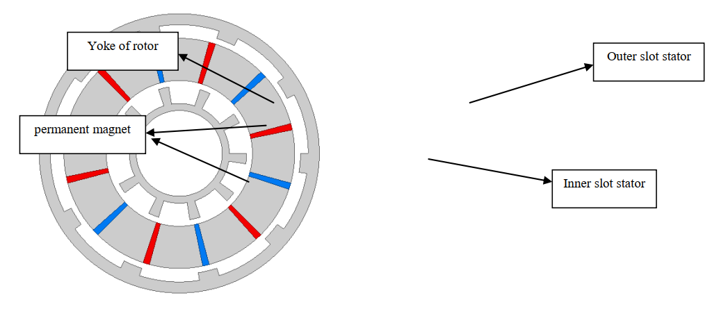
Figure 7. Cross section of modeled machine
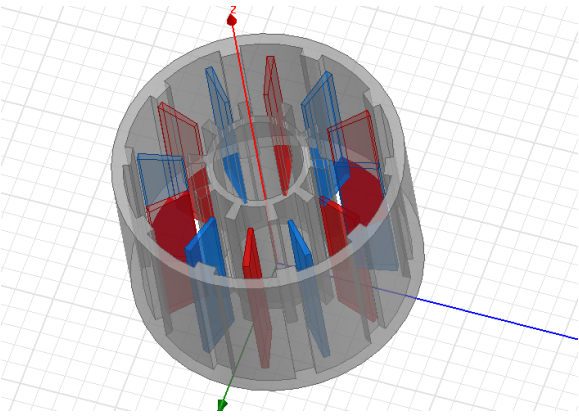
Figure 8: 3-dimenisonal of modeled machine
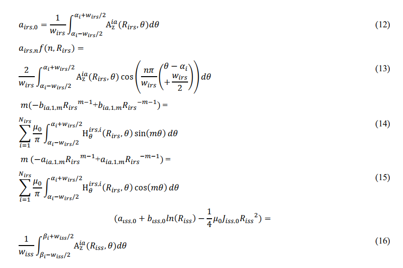
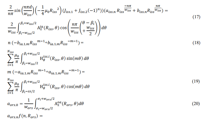
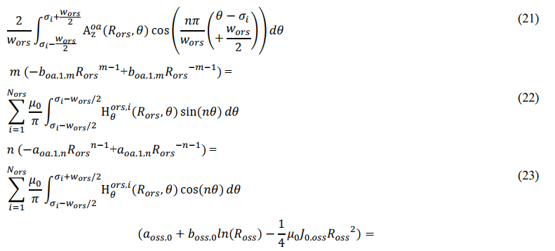
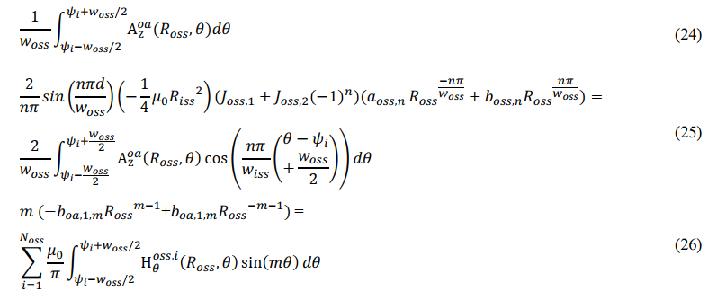
1.2 Governing Relations
The Maxwell equation for a sub-region having both current density and PMs is expressed as follows:
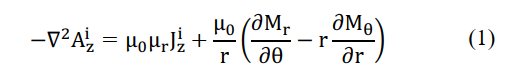
It is informed that in the PM sub-regions Jz=0, and in the winding sub-regions Mr= = 0. For other
sub-regions both J and Mare zero, as shown in the following expression:
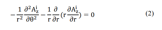
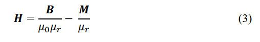
The magnetic flux density components are in accessibility for each sub-region by using curl from the
magnetic vector potential, i.e.B= x A,and the magnetic field intensity is calculated by (3) that for PM regions M is not zero and for the other regions M=0.
1.3 Boundary Conditions
The magnetic vector potential is continuous at the interface between two neighbor regions. If the interface is source-free, as result the parallel component of the magnetic field intensity vector on one side of the boundary is equal to that of the other side in according to table1 . Also, the parallel component of the magnetic field intensity vector is zero at the interface of those media adjacent to infinitely permeable domains that solving the nonlinear equations are done by Shwarz-Christoffel formula [35-43].

2. Results
To show the validation of the categorized analytical magnetic field expressions, a SRDSIPMBSMWSTS with the specifications listed in Table 2 is selected as the case study. The proposed model can be used to accurately analyze the influence and interference of the inner part on the outer part and vice versa. Outputs are shown in figures that horizontal index for whole results are between 0 to 180 degrees.
| Parameters | Value |
|---|---|
| Number of inner phases,Niph | 3 |
| Number of outer phases,Noph | 3 |
| Number of inner stator slots,Nirs | 10 |
| Number of outer stator slots,Nors | 10 |
| Number of PMs,Npm | 12 |
| Relative permeability of PM, μrpm | 1 |
| Residual flux density,Brem | 1.2T |
| Inner rotor yoke radius,Riry | 26mm |
| Outer rotor yoke radius,Rory | 102mm |
| Inner stator yoke radius,Risy | 60mm |
| Outer stator yoke radius,Rosy | 75mm |
| Inner radius of inner stator,Riss | 38mm |
| Outer radius of outer stator,Ross | 92mm |
| Inner radius of outer rotor,Rors | 96mm |
| Outer radius of inner rotor,Rirs Width of inner slot slot,wirs |
35mm 27 π/180 rad |
| Width of outer stator slot,wors | 27 π/180 rad |
| Width of PM,wipm | 3.2 π/180 rad |
| Stack length,Ls | 100mm |
| Filling factor,Kf | 0.5 |
| Inner rotor speed | 167rpm |
| Outer rotor speed | 167rpm |
Table 2. Specifications of the Srdsipmbsmwsts
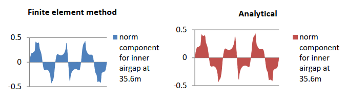
Figure 9. Comparison between analytical model and FEA for normal component of flux density at 35.6mm
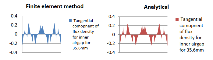
Figure 10. Comparison between analytical model and FEA for tangential component of flux density at 35.6mm
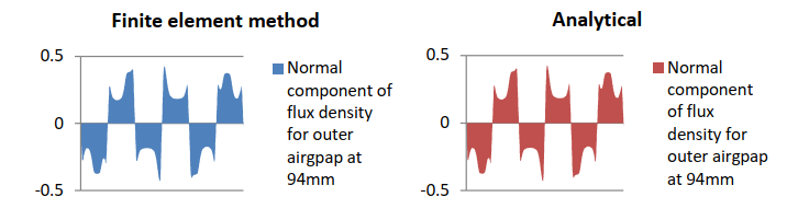
Figure 11. Comparison between analytical model and FEA for normal component of flux density at 94mm
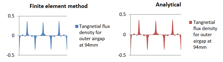
Figure 12. Comparison between analytical model and FEA for tangential component of flux density at 94mm
3. Conclusion
In this paper, a global formulation of the analytical model has been clarified and formulated to yield the magnetic field distribution and finally, analytical results are in good agreement with those obtained by FEM.
Declarations
Ethical Approval
I hereby declare that this thesis represents my own work which
has been done after studying at university of Bojnourd, and has not been previously included in a thesis or dissertation submitted to this or any other institution f r a degree, diploma or other qualifications. I have read the research ethics guidelines, and accept responsibility for the conduct of the procedures in accordance with Springer journal. We confirm that we have given due consideration to the protection of intellectual property associated with this work and that there are no impediments to publication, including the timing of publication, with respect to intellectual property. In so doing we confirm that we have followed the regulations of our institutions concerning intellectual property. We further confirm that any aspect of the work covered in this manuscript that not has involved either experimental animals or human patients. We understand that the Corresponding Author is the sole contact for the Editorial process (including Editorial Manager and direct communications with the office). We confirm that we have provided a current, correct email address which is accessible by the Corresponding Author.
Competing Interests
This research is sponsored by [Bojnourd University] and may lead to development of products.
Authors' Contributions
The authors confirm contribution to the paper as follows: Ehsan Shirzad oes all of the works.
Funding
This research received no specific grant from any funding agency in the public, commercial, or not-for-profit sectors.
Availability of Data and Materials
No datasets were generated or analyzed during the current study
Appendix
Nomenclature
| A Magnetic vector potential (V.s/m) | r Radial direction |
| B Magnetic flux density vector (T) | Tangential direction |
| B Br Radial component of B (T) | z Axial direction |
| B Tangential component of B (T) | iry Inner rotor yoke |
| H Magnetic field intensity vector (A/m) | ia Inner airgap |
| J Armature current density vector (A/m2) | iss Inner stator slot |
| μ0 Free space permeability (H/m). | isy Inner stator yoke |
| μr Relative permeability | osy Outer stator yoke |
| μr Relative permeability | osy Outer stator yoke |
| Niss Number of inner stator slots | oss Outer stator slot |
| Noss Number of outer stator slots | oa Outer airgap |
| αi Central angle of ith slot of inner rotor | ors Outer rotor slot |
| βi Central angle of ith slot of inner stator | ory Outer rotor yoke |
| σi Central angle of ith slot of outer rotor | m, n, v, k Harmonic order |
| ψi Central angle of ith slot of outer stator | a,b,c,d,e Unknown coefficient |
| Гi Central angle of ith slot of permanent magnet | Width of slots of inner rotor |
| Гi Central angle of ith slot of permanent magnet | Width of permanent magnets |
| Width of slots of inner rotor | |
| ∫ Width of permanent magnets |
References
- Sikder, C., Husain, I., & Ouyang, W. (2015). Cogging torque reduction in flux-switching permanent-magnet machines by rotor pole shaping. IEEE Transactions on Industry Applications, 51(5), 3609-3619.
- Dupas, A., Hlioui, S., Hoang, E., Gabsi, M., & Lecrivain, M. (2016). Investigation of a new topology of hybrid-excited flux-switching machine with static global winding: Experiments and modeling. IEEE Transactions on Industry Applications, 52(2), 1413-1421.
- Li, S., Li, Y., & Sarlioglu, B. (2015). Partial irreversible demagnetization assessment of flux- switching permanent magnet machine using ferrite permanent magnet material. IEEE Transactions on Magnetics, 51(7), 1-9.
- Zhang, G., Hua, W., & Cheng, M. (2016). Rediscovery of permanent magnet flux-switching machines applied in EV/HEVs: Summary of new topologies and control strategies. Chinese Journal of Electrical Engineering, 2(2), 31-42.
- Cao, R., Jin, Y., Zhang, Y., & Cheng, M. (2016). A new double-sided HTS flux-switching linear motor with series magnet circuit. IEEE Transactions on Applied Superconductivity, 26(7), 1-5.
- Du, Y., Zou, C., Zhu, X., Zhang, C., & Xiao, F. (2016). A full-pitched flux-switching permanent magnet motor. IEEE Transactions on Applied Superconductivity, 26(4), 1-5.
- Enwelum, M. I., Sulaiman, E. B., & Khan, F. (2016). Optimization of 12S-14P permanent magnet flux switching motor (PMFSM) for electric scooter application. In 4th IET Clean Energy and Technology Conference (CEAT 2016) (pp. 1-6). IET.
- Gandhi, A., & Parsa, L. (2016). Double-rotor flux-switching permanent magnet machine with yokeless stator. IEEE transactions on energy conversion, 31(4), 1267-1277.
- Jia, H., Wang, J., Cheng, M., Hua, W., Fang, C., & Ling, Z. (2016). Comparison study of electromagnetic performance of bearingless flux-switching permanent-magnet motors. IEEE Transactions on Applied Superconductivity, 26(4), 1-5.
- Kim, D., Hwang, H., Bae, S., & Lee, C. (2016). Analysis and design of a double-stator flux-switching permanent magnet machine using ferrite magnet in hybrid electric vehicles. IEEE Transactions on Magnetics, 52(7), 1-4.
- Li, H., & Zhu, H. (2016). Design of bearing less flux-switching permanent-magnet motor. IEEE Transactions on Applied Superconductivity, 26(4), 1-5.
- Xiang, Z., Quan, L., & Zhu, X. (2016). A new partitioned rotor flux-switching permanent magnet motor with high torque density and improved magnet utilization. IEEE Transactions on Applied Superconductivity, 26(4), 1-5.
- Wang, Z., Xu, W., & Ye, C. (2016). In-wheel outer rotor flux switching permanent magnet machine with fractional-slot concentrated windings for electrical vehicles. In 2016 IEEE Conference on Electromagnetic Field Computation (CEFC) (pp. 1-1). IEEE.
- Kim, J. H., Liu, M., Ding, H., & Sarlioglu, B. (2017). Comparison of dual structure axial flux-switching permanent magnet machines. In 2017 IEEE Energy Conversion Congress and Exposition (ECCE) (pp. 328-333). IEEE.
- Lu, Q., Yao, Y., Shi, J., Shen, Y., Huang, X., & Fang, Y. (2017). Design and performance investigation of novel linear switched flux PM machines. IEEE Transactions on Industry Applications, 53(5), 4590-4602.
- Syed, Q. A. S., Kurtović, H., & Hahn, I. (2017). New single-phase flux switching axial flux permanent magnet motor. IEEE Transactions on Magnetics, 53(11), 1-5.
- Yu, D., Yunyun, C., & Linlin, Y. (2017). Design and comparison of double-stator and conventional flux switched permanent magnet motor. In 2017 20th international conference on electrical machines and systems (ICEMS) (pp. 1-4). IEEE.
- Sh n, Y., Lu, Q., Li, H., Cai, J., Huang, X., & Fang, Y. (2017). Analysis of a novel double-sided yokeless multitooth linear switched-flux PM motor. IEEE Transactions on Industrial Electronics, 65(2), 1837-1845.
- Zhao, W., Chen, D., Lipo, T. A., & Kwon, B. I. (2015). Dual airgap stator-and rotor-permanent magnet machines with spoke-type configurations using phase-group concentrated coil windings. IEEE transactions on industry applications, 53(4), 3327-3335.
- Luo, J., Zhao, W., Ji, J., Zheng, J., Zhang, Y., Ling, Z., & Mao, J. (2017). Reduction of eddy-current loss in flux-switching ermane t-magnet machines using rotor magnetic flux barriers. IEEE Transactions on Magnetics, 53(11), 1-5.
- Gan, C., Wu, J., Shen, M., Kong, W., Hu, Y., & Cao, W. (2018). Investigation of short permanent magnet and stator flux bridge effects on cogging torque mitigation in FSPM machines. IEEE Transactions on Energy Conversion, 33(2), 845-855.
- Liang, Z., Gao, Y., Li, D., & Qu, R. (2018). Design of a novel dual flux modulation machi e with c n equent-pole spoke-array permanent magnets in both stator and rotor. CES Transactions on Electrical Machines and Systems, 2(1), 73-81.
- Yang, H., Zhu, Z. Q., Lin, H., & Lyu, S. (2018). Comparative study of hybrid PM memory machines having single-and dual-stator configurations. IEEE Transactions on Industrial Electronics, 65(11), 9168-9178.
- Cao, R., Jin, Y., Lu, M., & Zhang, Z. (2018). Quantitative comparison of linear flux-switching permanent magnet motor with linear induction motor for electromagnetic launch system. IEEE Transactions on Industrial Electronics, 65(9), 7569-7578.
- Ding, Q., Ni, T., Wang, X., & Deng, Z. (2018). Optimal winding configuration of bearingless flux-switching permanent magnet motor with stacked structure. IEEE Transactions on Energy Conversion, 33(1), 78-86.
- Hu, H. J., Cao, G. Z., Huang, S. D., Wu, C., Guo, J. C., Liang, D. L., & Mai, R. K. (2018). Design and analysis of a planar flux-switching permanent magnet motor. IEEE Transactions on magnetics, 54(11), 1-6.
- Yang, H., Lin, H., Li, Y., Wang, H., Fang, S., & Huang, Y. (2018). Analytical modeling of switched flux memory machine. IEEE Transactions on Magnetics, 54(3), 1-5.
- Yıldırız, E., Güleç, M., & Aydın, M. (2018). An innovative dual-rotor axial-gap flux-switching permanent-magnet machine topology with hybrid excitation. IEEE Transactions on Magnetics, 54(11), 1-5.
- Yang, H., Zhu, Z. Q., Lin, H., Fang, S., Huang, Y., & Xu, Z. (2018). Novel dual-stator switched-flux memory machines with hybrid magnets. IEEE Transactions on Industry Applications, 54(3), 2129-2140.
- Cao, R., Yuan, X., Jin, Y., & Zhang, Z. (2019). MW-class stator wound field flux-switching motor for semidirect drive wind power generation system. IEEE Transactions on Industrial Electronics, 66(1), 795-805.
- Mo, L., Zhu, X., Zhang, T., Quan, L., Lu, Q., & Bai, X. (2018). Loss and efficiency of a flux-switching permanent-magnet double-rotor machine with high torque density. IEEE Transactions on Magnetics, 54(11), 1-5.
- Tan, Q., Wang, M., & Li, L. (2021). Analysis of a new flux switching permanent magnet linear motor. IEEE Transactions on Magnetics, 57(2), 1-5.
- Sokolov, M., Saarakkala, S. E., Hosseinzadeh, R., & Hinkkanen, M. (2020). A dynamic model for bearingless flux-switching permanent-magnet linear machines. IEEE Transactions on Energy Conversion, 35(3), 1218-1227.
- Shirzad, E. (2023). Sub-Region Model for Flux-Switching Permanent Magnet Machine with Outer Rotor and Inner Rotor Distinctly to Calculate Cogging Torque, Electromagnetic Torque and Inductance (self and mutual).
- Shirzad, E. (2023). Optimized Design by Genetic Algorithm for Flux Switching Brushless Permanent Magnet Machines with Two Ports from Perspective of Losses.”
- Shirzad, E. (2023). UPS design without inverter to power ISP servers.”
- Shirzad, E. (2023). Calculation of Flux density in Air Gap for Reluctance Motor with Two Ports (Double-Stator, Double-Rotor) by Fourier Series.”
- Shirzad, E. (2023). Solving Partial Derivation Equations in Detail in Double-Rotor Flux Switching Permanent Magnet with H-Shape Stator Machines to Obtain Magnetic Flux Density.”
- Shirzad, E. (2023). Analytical model for double-sided linear permanent magnet inner armature synchronous machine with slot-less stator at on-load in different patterns of magnetization. Electrical Engineering, 1-15.”
- Shirzad, E., & Rahideh, A. (2021). Analytical model for brushless double mechanical port flux-switching permanent magnet machines. IEEE Transactions on Magnetics, 57(10), 1-13.
- Shirzad, E., Pirouz, H. M., & Shirzad, M. T. (2023). Subdomain method for brushless double-rotor flux-switching permanent magnet machines with yokeless stator. Electrical Engineering, 1-11.
- Shirzad, E., & taghi Shirzad, M. (2022). Multilevel Optimum Design of Double Rotor Brushless Flux-Switching Permanent Magnet Motor.”
- Shirzad, E. (2022). Fast-Response Method for E-core switched-flux permanent-magnet brushless machine with
Outer Rotor to Predict Distribution of Flux density at No-Load.”
Copyright: ©2023 Ehsan Shirzad. This is an open-access article distributed under the terms of the Creative Commons Attribution License, which permits unrestricted use, distribution, and reproduction in any medium, provided the original author and source are credited.